Pages

Sunday, December 28, 2014

your library has tools

I found that my local library has energy monitoring tools available to borrow. You should check at your own library.

I recently learned that it is possible to borrow a thermal imaging camera and other renewable energy tools from the Medicine Hat Public Library (see this from the Medicine Hat, AB HATSmart).

Other tools mentioned are an infrared thermometer, a power cost monitor and a watt meter. They are loaned like other library assets, handled with the normal system.

These are tools that the average homeowner might use if they were aware of how to properly use them to spot energy leaks. Some, like the thermal imaging camera, the average homeowner likely would not buy for their own use because of high cost. Rentals are not commonly available outside the "big city". Borrowing from the local library makes a lot of sense.

Were such tools available from my own library system?

I asked Erin at the local Lion's Head, ON library yesterday about borrowing renewable energy tools.

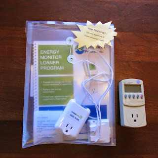
Erin showed me an electrical monitor which I borrowed to compare to my own (kill-a-watt). They have one of these Trickle-Star units in a kit with some useful publications at every branch through a program sponsored by Westario Power. Two Westerio publications "Energy Conservation Handbook" and "Energy Monitor Loaner Program" as well as the Trickle-Star user manual are included in the loaner kit.

Erin thinks they have one of the IR spot thermometers available.

Interestingly, she was not sure how to look these things up. On my library receipt, the call number for trickle-star is "BCPL energy monitor", the title is "Energy monitor loaner program". I have it for a week and will do some testing with it. You can reserve it through the BCPL on-line library.

My library also has a geocaching kit complete with GPS that you can borrow and there is some talk of buying a 3D printer!

The Medicine HAT Smart website has lots of useful information and is worth having a look.

I would be interested in what you find at your own library. Please use the comment form below.

I came across Medicine Hat while reading about the new Medicine Hat first concentrating solar power plant in Canada.


George Plhak
Lion's Head, Ontario, Canada

Your comments are always welcome. You can use the form below (comments are moderated and will appear a short time after you post - prevents spam)

Friday, October 24, 2014

weatherproof rotation switches from recycled thermostats

A good source for rotational switches can be had in old thermostats which contain a mercury switch or two.


An old thermostat contains a mercury switch which you can use to sense mechanical rotational position. This is especially valuable for outdoor projects since the switches are sealed. I am intending to use these for low voltage (about 12 volts) control where the switched current won't be more than an amp.

I am replacing 80s technology with recycled 90's tech. At my house, I have replaced the existing clock motor thermostat (the clock did not work) with a "new" (to me) Honeywell/34 that had been removed from a church. The date on the "new" manual is 1994. According to the manual: this thermostat is actually a small but powerful computer. So far it is working fine. The default temperature of 20C is a bit too warm but nice as I enjoy the heat while it is not too cool outside. The furnace is not working hard yet, the outside temp is about 5C. Replacing a thermostat is best done on a day when you don't actually need the heat.

In this old Honeywell Chronotherm the single mercury switch is to the right on a tilt-able mount which is attached to the set temperature lever. The black thing with two wires hanging out the left side looks and feels like a battery. Is it possible that is a DC operated clock?

A closer view of the mercury switch, the small glass vial up and to the right to the right of the colored plastic post. I would like to remove the vial and it's wires without damage. I'll have to study it a bit and report back.

SAFETY REMINDER: Mercury is toxic and we must take a lot of care NOT TO BREAK THE VIAL and let the mercury escape. It is best to work over a pan so that should the vial be damaged, the mercury will escape into the pan. Keep a pill bottle handy for any escaped mercury metal.

In North America, you are more likely to see round Honeywell thermostats, like the T87 (complete data sheet here). It comes apart easily by undoing the single long screw that holds the adjustment post in place.

Recently, I rescued three T87 from a lighthouse that had new heating installed. Thank you Cabot Head. Three is ideal since if I have trouble with any one I will still have the two I need.

When I removed these from the wall, I did not know that there were three screws to remove the dome from its base so some damage resulted, mostly to a metal wiring terminal post but that won't matter for removal of the mercury switch.

Here is the T87 dis-assembled with the mercury switch on its thermal spring. The wire terminals are clean and undamaged. The drop of mercury is in the glass vial which is not chipped or cracked. With this one, the glass vial can be separated from the mounting clip, it just slides out the fingers, they haven't used any glue. But I think that we can make use of the clip assembly to mount our mercury switch.

Could we use the whole tilt-able mount assembly to have a fine adjustment built in to our own mount? For what I have in mind I don't want temperature to be a factor so I would like to replace all or most of the bi-metal spring which is the sensing element for temperature in this thermostat. Newer ones use a thermistor or a semiconductor sensing element and they don't contain a mercury switch.

One possible use of these type of switches is for limit switches in a solar tracking array or for a float switch.

Mercury switches (in the box at the red arrow) are used to limit the rotation of the array in the pic of a parabolic solar collector.

Two mercury switches cut off motor current when the array tilts over as far as it should go. To go further will cause metal parts to jam together. Stalling the motor uses a lot of power uselessly so it is best to avoid hitting the mechanical limit. The mercury switches help prevent that.

It is not possible to easily buy mercury switches since they have all but been banned for new construction. However by gathering these as they are being removed from service saves them from the landfill and keeps them available for a future use.

Link here goes to the motor drive of the project. The main index is diy solar parabolic trough gen2 intro

George Plhak
Lion's Head, Ontario

Friday, July 11, 2014

solar bbq

This home built solar cooker is a parabolic solar reflector with a spit rod at the focus. A simple aligner post at the bottom front shows clearly when it is perfectly aimed at the sun. Aiming seems not that critical and the post makes it easy. We checked and moved very slightly only once during 1/2 hour of cooking.

Today was the first time I was able to try it. For my test, I cooked one hot dog to perfection. The test was done again the next day with four hot dogs. I would like to do a non-meat test.

Two things weren't perfect: I'd started cooking in the late afternoon, at about 4pm as the sun was already part way down the sky. Also, the reflective surface is not a mirror finish but shiny aluminum roofing flashing as it comes off the roll which might give I think about 1/2 performance, yet a useful test in itself. In spite of these two factors, I had a steaming hot dog (160F) in about a half an hour. I was hoping to be able to grill somewhat (brown the surface) but that didn't happen, it did not get hot enough. I will use a mirror film shortly and start cooking earlier in the day.

I can heat small objects which skewer onto the thin stainless rod which slides into a slot along the focal line. I used a round stainless rod but a square, flat, oval or triangular cross section might work better since the payload (what's on the spit/skewer) has a tendency to slide around on the round road as it cooks and shrinks.

The characteristics of the surface of what I put on the spit will determine how it heats. I thought that this might be useful for marshmallows but their bright white color makes it almost certain that they will reflect away most of the heat.

The aiming is manual. The small disk with a perpendicular dowel makes a sensitive indicator of the sun's position. If the shadow is small and falls almost directly near the dowel, the aim is good and the sun's concentration achieved is about 18 times.

click any picture to enlarge

Aiming disk. The shadow of the small dowel on the disk shows less than perfect alignment and gives an indication of which way the bbq should be turned in order to point more directly at the sun. In practice, the aiming is not super critical. If the shadow is within about 5cm of the dowel, this is good enough. We moved the trough only once in the half hour and probably didn't need to do that.

View of the rear. I am using a video camera tripod which makes an excellent mount. Not a polar mount but it gets the job done. I have attached a small plate with a captured nut the same as on the bottom of cameras (1/4-20) so I attach the bbq to the stand with one screw, the regular one used to attach a camera to the stand.

Trying again today with four dogs and starting mid-day. My assistant Justin is showing how bright it is standing close to the reflector. We have put a strip of aluminum foil over the bottom third (it is not very smooth) to see if it was more reflective than the aluminum roof flashing (if dogs heat quicker over the foil) and possibly to catch any drips.

One of the dogs after about 25 minutes. The glisten makes it difficult to measure the temperature with an optical temperature meter, there is scatter depending on how it was pointed. Done as before by removing the spit from the bbq and moving it to a shady area to measure.

It is hottest closest to the spit. It would not be effective, for example to thread the hot dogs onto the spit through their radial center as opposed to lengthwise, through their axial center even though it might seem to increase the capacity of the bbq (more hot dogs cooked at once?).
With the aluminum roll flashing as the reflector, I estimate about 200 watts of cooking power available. This could possibly reach 400 watts with a mirror reflector.

The finished product. Could be used also for kebabs or other long, narrow items.Temperatures as high as 160F to a low of about 70F so I don't have faith in the measurement. The dogs were warm to the touch and mouth though and already cooked (according to the package). I would still like to broil them so need to get mirror material for the reflector.

Still, I am encouraged to see that this works. If you only had access to roof flashing and a bit of plywood, some straight angle metal (aluminum, steel, plastic, fiberglass etc), a workable spit bbq can be achieved at very low cost. The cost of the materials as I did it (not including the tripod) is about Cdn$10-$25. Using flexible mirror in place of the roof flashing might double cost but improve performance, probably near double (will cook faster and hotter).

This is an example of what can be done with the gen2 design in a simplified version. The gen2 book is available here in either downloadable or paper version.

Monday, June 09, 2014

clothes dryer heat recovery

This easily built project recovers warm moist air from a clothes dryer that would otherwise be exhausted to the sub-zero outside.

Energy is saved two ways: heat used to dry clothes remains in the house and less cold air is drawn in by preventing negative pressure. Electrical energy that is used to dry clothes contributes to house warming. Moisture that is added to the house air is welcome during a northern winter when the cold temperature outside causes the air in the house to become very dry.


I only use this in winter. In the summer, I re-route the vent to the outside but I use the clothes dryer only on rainy days. I use the outdoor clothes line whenever possible. I also have a indoor clothes line which is used on damp days and even in the winter.

My clothes dryer is used as little as possible as it uses an enormous amount of electrical energy. The nameplate on mine lists 25 amps at 240 volts or (25x240=) 6000 watts. When I do use it, it is good to know that the expensive heat is used twice by not being blown outside.

I made a simple box of scrap wood with a slot in one side to insert and remove a standard furnace air filter. The size of the box is determined by the size of the furnace filter. In my case, I used the same filters as my heating furnace so the inside dimensions of the box are 20x20 inches by about four inches deep. The slot is 1 inch wide to accommodate the filter. See the video below for more details.

The box has wood battens inside along three sides to guide and support the filter. On the side opposite the slot, facing downward, a right angle 4 inch heater duct fitting is attached to feed air from the dryer into the box.

The box has a plywood back and is attached to the wall above the dryer with two wood screws. Heated moist air comes into the box through a flexible aluminum pipe attached to the duct and exits through the filter into the room.

The entire box is primed and painted with ordinary house latex (water based) paint for moisture protection.

Installation involved removing the existing aluminum flex hose from the wall and attaching it to the duct on the bottom of the box.

I then filled the existing exhaust hole through the wall with fiberglass insulation.

As I did this I thought about what a heat loss this hole represented with it's aluminum tube to the outside wall. Another benefit of the project is to effectively seal up this leak to the outside for the winter.

This is the existing flex and rigid pipe as removed from the dryer after re-attachment to the bottom duct of the heat recovery box instead of to the outside vent. The dryer was then plugged in and the hose attached before sliding it into place.

Some of you with larger families who live in climates with warm, damp winters may prefer an approach using a heat exchanger to remove the moisture from the air before it is released into the house. Here are two approaches: one by Gary Reysa at builditsolar and another by ALK Engineering. I think that you will agree that these are quite a bit more complex than the my simple approach but as I said, I welcome the moisture and don't have very much of it. I can tell if I have excess moisture easily when I see condensation on the windows in the same room. With one load at full heat with -15C outside, the moisture from the clothes dryer dissipates throughout the house and does not normally condense on the cold window.

You can buy commercial heat recovery units at the Home Centers like this one from Jafine.

Simple, like mine, this is a plastic box with a diverter valve and a nylon sock to catch the lint. I have used one of these in another home and it does work.

It's a pretty cheap product though and messy to clean. I spent less money on my home made project. I think mine looks and works better and will probably last longer.

Please watch this video showing some views of my project.


Thank you for your interest.

George Plhak
Lion's Head, Ontario, Canada

Update June 20 2019:

What it looks like when the filter gets changed.

The old filter slides out the side. A bit of work with a vacuum cleaner to clean up the box. This is after about a year.

Carry the filter outside as gently as you can to not disturb all the fluff.

Amazing how much lint is caught even after the lint filter in the appliance. Normally this would be vented outside or clogged in the outlet pipe.

I fold them over an put in the garbage. I don't think these are recyclable?

Thursday, April 17, 2014

a shielded low power diy garden lamp

Much is written about the benefits of shielded "dark sky" lighting. The main benefits are reduced light pollution, improved security and reduced energy use. You can read more about the dark sky movement at Wikipedia.

Shielded light fixtures focus light downward where it does the greatest good. No light is allowed upward into the night sky or over into a neighbor's property. Lower light levels produce less glare and save energy. Less glare makes for better security since it is easier to see intruders without being blinded by a bright, exposed light source.

Health benefits are also claimed, for humans and our animal friends. See Scotobiology.

I was challenged to make a shielded version of my Do It Yourself (DIY) garden lamp. My lamps already use very little power, adjustable from 1 to 10 watts yet produce a surprisingly bright field of illumination. Since the LED is mounted up inside the lamp, no vertical light escapes (light above the horizon) but because of the glass diffusers being exposed, some light does escape horizontally. I wanted to show a design that controlled the light in a manner consistent with the definition of a shielded lamp.

Construction

Continuing with my theme of using commonly available recycled materials where ever possible, I visited the local recycling store and purchased a rather used medium sized stainless steel mixing bowl with a flat bottom and a squat jelly jar. Total cost $1.25.

The jelly jar will provide protection for the LED and some light diffusion. The lid of the jar will be mounted on the flat in the bottom of the bowl so it was important that the jar lid diameter was less than the diameter of the flat part of the bowl.

It would have been better to use a spun aluminum bowl instead of the stainless steel because the bowl will also function as the heatsink for the LED. At lower power that is not really necessary and the steel will work well as a heatsink but at 10 watts and above in a hotter climate, the aluminum would be a better choice if you have that option. It seems that stainless steel bowls are most common although I do have some aluminum bowls from IKEA. I will check at IKEA on the next trip to see what they have available.

These are the basic parts less the LED and wire. The jelly jar is shown where it will be mounted, at the center of the bowl. The L-bracket is made of ordinary framing lumber. What I had at hand was some pressure treated 2x6 but I could have used pine, cedar or any wood of pretty much any thickness or width.

I cut one end of the support arm round to match the flat bottom of the bowl and you should be able to see the cross hair I marked to show where the center of the bowl will mount to the arm (click any picture for an enlarged view).

The arm is screwed to the upright with two deck screws. I pre-drilled smaller holes to help line the two pieces up and to help prevent splitting of the wood.

As with all my projects, even though this is a prototype, I smoothed the cut edges with a file and then some sandpaper to make for a more finished appearance. Generally I don't apply a finish. I prefer to let my outdoor lamps turn grey for a weathered natural look but you can finish yours in any way your like or leave them rough. You could use reclaimed wood or new. The cost of new wood and the two deck screws would be about $1.

I need the multiple holes I am going to drill through the jar lid and the bowl to line up precisely. First, I found the center of each and drilled one hole just slightly larger than a small bolt (I used a 4-40 or M2 bolt and nut) to fasten the jar and the bowl together temporarily. I then marked the location of the three holes that will ultimately hold the wood screws fastening the jar and bowl to the arm.

In this picture, I have inserted the same type of machine screw and nut in all four holes to check that they all line up.

I am going to take this apart after the holes are drilled. You can see that I marked ONE of the outer holes with a marker to distinguish it on both the lid and the bowl so that I can reassemble in the same orientation so everything stays lined up. The marker shows the front hole, the one that will be toward the front of the lamp.

In this picture, I have removed the center bolt and nuts, marked the locations of the mounting holes for the chip LED and I am drilling those holes with the jar lid and the bowl still screwed tightly together with the three outer bolts and nuts to ensure accuracy of the through holes for the LED.

Since the LED I am using relies on bolts at it's edge to hold it in place, these holes must be the most accurate of all. The LED must be firmly held to the jar lid to allow the heat it produces at higher power to be dissipated. If it cannot get rid of it's heat, it will overheat and fail. I will also coat the bottom of the LED with thermal grease and the corresponding area where the jar joins the bowl to help with heat dissipation.

One final, larger hole drilled through both the jar lid and the bowl will allow the wire to pass into the jar to be attached to the LED. I then remove the three screws, take the jar lid and the bowl apart and remove any burrs and chips from the drilling.

Reassembled in this view with the three bolts and nuts and the smaller bolts and nuts holding the LED in place. I have attached the wire to the LED with solder. I do not use connectors if possible on outdoor construction since I feel that a hard soldered connection is going to provide better reliability.

You will see that I have marked the negative wire (the one attached to the negative terminal of the LED) with a small piece of black heat shrink. I have also marked the other end of the same wire with another piece of heat shrink. Since the LED is a DC device, it must be hooked up in the correct orientation. The LED will not produce light if it is hooked up backwards.

In this view, I have the jar lid and bowl screwed to the arm. I have removed the three bolts and nuts, lined up the holes and attached the jar lid and bowl to the arm with three small wood screws through the same three holes.

In this side view, you can see a shallow channel I have cut in the arm to pass the wire along so that it comes out of the back of the arm. In a later version I will fill the channel with caulking to hold the wire in place.

I have pre-drilled holes in the upright piece of wood to make it easier to attach the lamp to a post on the deck.

A final step, before taking the lamp outside to installwas to take it over the electronics bench to attach power to make sure the lamp was wired correctly. It worked the first time! While at the bench, I checked the light pattern with and without the jar fitted.

Performance

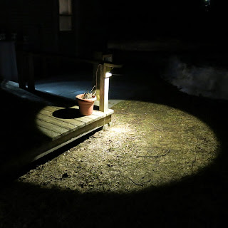
The lamp gives a pleasing warm white illumination with a very sharp cutoff.

The lamp in the picture is mounted about 2.5 feet up a post at the side of the deck. At this height it brightly illuminates a circular area about nine feet in diameter. There is very little spill, as can be seen.

In this test, I am driving the LED at about 9 volts from a recycled 9 volt DC "wall wart" power supply from the recycling center.

The LED I am using is the "10 watt" LED chip described in this article. From the spreadsheet testing results I gave in this article, the LED should be running at about 3.2 watts at this voltage. This is about the mid-range for this LED chip. I could run it at 1 watt and still have very usable light or comfortably up to 10 watts for much brighter illumination.

The Lighting Research Center Rensselaer Polytechnic Institute, Troy, NY gives definitions for Full Cutoff, Semicutoff and Noncutoff as well as the difference between full cutoff and fully shielded. Who knew that lighting could be so complex?

In order to properly classify my light, I will have to draw some circles on the ground and get out my lightmeter. I prepared this illustration based on the bowl I used from the recycling center. The cutoff angle would of course be different depending on the dimension of any paricular bowl that was used, but these are the angles for my prototype.

External pictures of the shielded garden lamp


Thank you for your interest in my work.

George Plhak
Lion's Head, Ontario, Canada


diy landscape lamp reading list
a very bright 1 watt diy led garden light
making a lamp from a 2x4
best light at least cost - about testing bright diy leds at home
diy testing of led lamps
diy 1 watt led update
diy garden lamp progress
a shielded low power diy garden lamp - this article
diy lamp update


Monday, March 24, 2014

new book update 2

The new book is finished!

It is almost twice the length of the first book, 155 pages, +300 figures.

For more information click on the book cover to the right.

I have added a signup for my mailing list in the column on the right. Please add your contact info if you like.

Thank you for your interest.

George Plhak
Lion's Head, Ontario, Canada
[to the gen2 intro and reading list]

Friday, March 07, 2014

new book update

I am working hard on the new book. In fact, I am working on nothing else right now. I have set a target of the end of March to have it finished - carefully proofed and available for download. I think you will like it. I do hope you will like it.

I have added a lot of new material. You have seen quite of bit of my work here on the blog and I am carefully integrating and updating the new. For background on the gen2 version please see this.

The first book was 90 pages. So far the second book is 130 pages and still growing.

I was telling someone recently my philosophy that it is better to tell the reader too much rather than not quite enough.

My to do list. Daunting since each of the items might take half a day or more to complete.

Included in the tasks are setting up a new webstore and reworking the website. I had promised that customers who bought the original book after May 1 2013 would receive a free download and there are quite a few of you - thank you! I have to pull together your email addresses and send you a unique code for your free download.

If you bought my original book before May 1, I will offer a discount on purchase of the second. You will receive a discount code also. I have never done this before so it will be a learning experience. Please bear with me.

Over the next few weeks I will be reworking the previews on the website so please check back.

I am quite proud of the new drawings which are hopefully clearer and easier to understand. Here is a sample, of the sensor support bracket (click any of my pictures here to see an enlarged view).

I am including with the book one large format pattern in .pdf form to help those who make the ribs and hangers manually (by hand). Because so many people had trouble finding a large format printer, I have included instructions for how to print the drawing and put it together in panels. You can see those instructions here (.pdf).

If you are lucky enough to have CNC available I will be including .dxf versions of these parts.

I NEED A BETA TESTER (OR TWO) WITH CNC equipment in the next two weeks who could check these three parts by making samples and to work with me to make sure all works as expected. The material does not matter, ordinary plywood would be fine for this, whatever you have available. You don't need to send me the parts but I would love some pictures and a few notes from you about how it went. Write to me if you are interested.

Finally, so many of you have said some very fine and touching things about my work. If you would like to read some of those comments, reproduced without edits exactly as I received them, you can read them here.

Thank you as always for your interest.

George Plhak, Lion's Head, Ontario, Canada

[to the gen2 intro and reading list]


Saturday, January 11, 2014

georgesworkshop diy weatherproof solar tracking sensor housing

A brief video tour of the solar sensor housing (radome) I made from a standard plastic outdoor electrical box and a hobby store transparent globe.

I had written previously about the housing here.

This sensor housing is mounted on a moving part of the georgesworkshop gen2 solar trough heater. It finds the position of the sun and steers the solar array toward it. A very simple commercially available circuit (US$35) provides all the brains that is required. The entire array uses only a small amount of 12 volts DC and can operate from a gel cel for a week or from a small solar PV panel. I used this array for solar heating of a swimming pool.

In this long view you can see the two locations I tried in the large array (click to enlarge photo).

Of the two spots, I now prefer the one at the top of the motor drive (the right lower arrow). Initially, I had decided to mount the sensor at the top left, since this was the earliest corner of the array to receive morning light and it worked fine.

I could have chosen any of the top or bottom hangers in the array to mount the sensor housing. There was an interesting failure that happened at the top left.

Lessons learned:.In a new appendix for the upcoming book, I discuss various things that went wrong with the gen2 design in the interest of sharing ideas that might improve your efforts. At left is the draft outline. I might add a few more things.

Here is a draft excerpt about melting the sensor housing, for your enjoyment:

"Appendix A - Lessons from Experience
In this section, I share with the reader some of the things that went wrong which were only evident with the passage of time.

Melting the sensor housing I wrote in the sensor section that the sensor housing should be located on a moving part of the array.
On the large swimming pool heater array, I chose to locate the sensor on a hanger at the top west end of the array since this corner received light first in the morning.

Here you can see that sensor backlit by concentrated sunlight streaming out of focus onto the solar sensor and its mount. This happens because I don’t have the array tilted quite high enough for my latitude.

Another view from the other side which shows the de-focused beam heating the side of the box and the deformation of the seal at the top.

...

Once the top of the Leviton box was removed, I could see that the side wall had deformed as well as looking a bit charred on the outside.

So the moral of the story might be to avoid the focus at the top of the array if possible? Having the sensor on a lower hanger might slightly shade a bit of the reflector but that location keeps the sensor housing out of the concentrated beam. Putting the sensor housing at the top of the motor drive arm, as I did with the Alternative 2 Round Sensor housing also protects the sensor from the beam."


As I said in the last post, I am going to be away from the workshop for a week.

Thanks for your interest.

George Plhak

[to the gen2 intro and reading list]