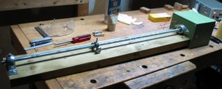
Here is the motor drive for the parabolic solar heater on the bench while I was running the yoke from one end to the other using the small DC lab power supply in the background.
You can click on any picture here to enlarge it.
The DC gearmotor is in the green box to the right. The output shaft of the gearmotor is coupled to the galvanized steel drive screw shaft inside the box. Both ends of the drive screw are supported with pillow block bearings, a flange mounted ball bearing unit (Dayton 4X727) at the motor box and a bronze bearing pillow block (Dayton 2X567) at the far end. That is an ordinary pressure treated 2x6 that forms the support. You can see the yoke assembly in about the middle of the screw. The limit switches haven't been added yet.
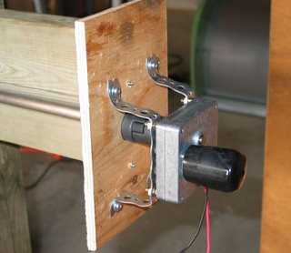
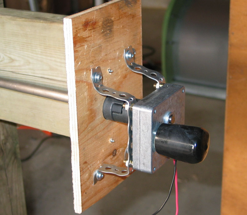
I don't have an up-to-date picture of the inside of the motor box, but here is a picture of an early version to show how simple it is. I used a Dayton 2L008 Permanent Magnet DC gearmotor with a 560:1 reduction ratio. Dayton products are available nationwide in Canada and the USA through Grainger Industrial Supply (
www.grainger.com). This motor only costs about $50 and is available from stock. It is rated for 12 VDC, and draws 1.2 amps at full load while turning 12 rpm. Only 15 watts to move the entire solar array! This little motor with the drive screw is plenty powerful enough for the job.
The 1/4" motor shaft is coupled to the 1/2" drive screw with a pair of spider couplers, like Woods L050 series which match the size of the two shafts and provide for a bit of mechanical misalignment if there is any.
I'm not that proud of the motor mounting which is just a pair of galvanized steel perforated strips, shaped to suit the motor distance back from the panel, but I was in a hurry to see it work and this seemed to do the trick. It's stayed that way for the last two years and works to hold the motor securely in place.
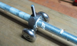
The yoke contains a captive 1/2 inch hex nut with the same thread pitch as the rod. The two outboard steel wheels just graze the 2x6 and keep the yoke from spinning around the drive rod.
The white goop on the thread and at the nut is white lithium grease. I connected the gearmotor to a DC supply and allowed the motor to turn steadily while I dabbed the white grease in it's path. To the left, you can see the grease spread out on the screw. I ran it back and forth over the whole distance I expected it to travel and kept dabbing grease on it until it was liberally coated smoothly and evenly. After two seasons, there is no rust and no apparent wear to the thread or the nut. I haven't re-applied the grease but probably will this spring.
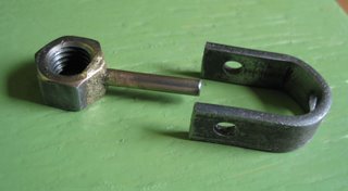
Here are the two main components of the yoke prior to threading and gluing. You can see that I have brazed a short section of 3/16" steel rod into a drilled recess in the hex nut. This was actually my second attempt, since I am not a welder. Prior to drilling the recess for the rod, I centerpunched a guide dimple for the drill on one of the hex edges. I found that it was important not to drill the pilot hole completely through the side of the nut so that the brazing alloy didn't flow through and clog the thread. I suppose that if I had had a tap of the appropriate size, I could have run it through the nut to clean up the thread afterwards, but I didn't have one at the time.

Here is the yoke with the steel rod threaded 10-32 and the nut glued into the 1/2 inch band iron frame with industrial epoxy. The two holes in the legs of the frame are for the steel wheels. The threaded rod couples to the actuator rod.
If I was a better welder, I might have brazed this whole assembly. Because of the large area beween the nut and the frame for the glue to grab, I had much better confidence in this approach. I am using an epoxy by Locktite called Hysol 907. It is amazing stuff, but does require suitable curing time (24 hours is recommended for full strength), or a heat cure (150 degrees F for about 2 hours). The surfaces to be glued should be roughed with silicon carbide sandpaper and cleaned with de-greaser prior to gluing.
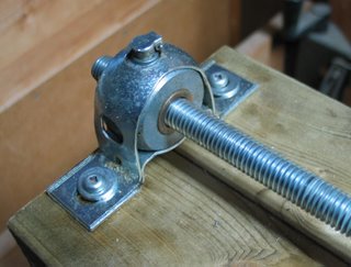
This is the pillow block which supports the far end of the drive screw. It is a bronze bushing which can pivot slightly in its housing to provide for some degree of mis-alignment. I used a bronze bushing pillow block out of concern for exposure to the elements. A sealed ball bearing unit was quite a bit more expensive and probably not necessary.
The oil cap is a nice touch and I even put a few drops of oil in it. The protruding oil cap did end up being a bit of a nuisance later as it interfered somewhat with the actuator rod which swings near it on it's way to the drive rod.

 Last year I spent about a month making new ribs and hangers carefully finished with epoxy primer and urethane topcoat. The new set of about 100 ribs and hangers (enough for 12 reflectors) is ready for assembly.