Pages

Thursday, September 29, 2011

2 Comparing concentrator to flat plate solar collector

In the previous test, the flat plate collector was fixed in position and it's performance compared to a tracking parabolic solar concentrator. In this variation, the flat plate was ganged to the tracking mechanism used for the concentrating collector so that they BOTH tracked the sun.

Flat plate thermal collectors are not normally rotated to face normal to the sun but it is commonly accepted that if tracking can be used, it will increase the effectiveness of the solar heating or PV. Since the mechanism was available (and necessary) for the concentrator, I decided to try rotating the flat plate collector.

In this view of the rear, the linkage that controls the position of the collectors can be seen. At the far end is the linear to angular motor drive that moves the assembly. The small pin with two screws parked temporarily on the beam is the stop that I used to lock the flat plate collector in a fixed position in the previous test.

At the beginning of this test I saw that the concentrator was partially shading the flat plate collector (see the first picture above). In spite of this partial shading, the flat plate started heating quickly.

As can be seen in the first picture above (best if you click it to see an enlarged view), the surface of the mirror was covered with water drops from the rain we had last night. This would tend to scatter the sun's light at the beginning of the test. I did not clean the mirror.

I also noticed at the beginning that the concentrator was not tracking true and the image of the sun was offset somewhat on the collector tube. This means lost heat as the sun's light does not completely fall on the collector. I noticed that the sensor housing had fogged somewhat and this may have contributed to the poor focus. I continued with the test. We don't get many great clear days anymore and winter is coming. I have more tests to do.

As is normal at this time of year here, the day was mostly sunny with clouds. There was almost no wind. By mid-afternoon however, the cloud cover was solid and at the end of the test, it had started to rain.

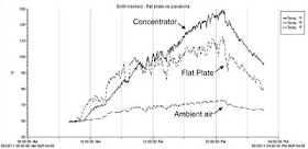
Here is the day's results with BOTH collectors tracked. As with the previous test, both collectors are UN-insulated. Tests of insulated collectors will be done next.

You will see that I added a channel for the ambient air temperature. That sensor is out of the sun under the deck, about four feet off the ground, not touching anything but air.

As noted, the flat plate starts to warm rapidly in spite of the partial shading which only lasted about 20 minutes into the test. As clouds pass overhead, the rapid cooling of the uninsulated flat plate noted in the previous test occurs here also. This is thought to be due to the large metallic surface area of the absorber plates. The concentrator is also uninsulated but it has much less metallic surface area so it does not cool as quickly.

By about noon, the concentrator reservoir temperature exceeds that of the flat plate and it remains higher for the duration of the test. The maximum is reached just before the sky completely clouds over at about 14:13 when the differential between the two reaches 17.45 F degrees (ambient is 72.4F). Even at the end of the test when light rain is occurring, the concentrator reservoir is still 16.9 F degrees higher than the flat plate with an ambient air temp of 66.9F.

I will be busy for a few days switching over to the insulated configurations for both the flat plate and the concentrator but I hope to have results from the next set of tests sometime next week.

Perhaps I should change the working fluid to 50/50 water/glycol in anticipation of winter? Brrr.

Index - Comparing concentrator to flat plate solar collector

Tuesday, September 27, 2011

1 Comparing concentrator to flat plate solar collector

A test is described which compares a traditional flat plate solar water heater made from copper tubing and aluminum fins to a parabolic concentrating collector. Both types can be home built for significantly less than the cost of commercial units. This test compares how each design heats an identical volume of water side by side in the same sun.

You can click on any picture here to see a full size enlargement.

I built the two collectors and mounted them in a test jig (described here) which can be oriented and tilted to face the sun. The collectors are connected to identical small insulated reservoirs which contain the same volume of water. During the test, the water is pumped from the reservoir through the collector and back to the reservoir. As the test progresses, the water in the reservoir heats up. My test is modeled after the technique described by Gary Reysa at BuildItSolar. As Gary says "The collector with the better performance heats the water in its reservoir to a higher temperature, and the difference in final temperatures in the two reservoirs is an indicator of how much better one collector performed than the other."

The parabolic concentrator design (parabolic trough) is my own and is described in my plan book How to build a Tracking Parabolic Solar Collector. The sun's energy reflects from a mirror bent in the shape of a parabola and is concentrated onto a single copper collector pipe which is positioned at the focus. The water flowing in the pipe is heated by conduction with the copper.

For this test, I used a half length four foot long reflector. It is in all ways the same as the full size version except for the length. The shorter version was chosen to make the test jig more manageable. The test jig incorporates the motor drive and solar sensor as described in the book. The motor drive can control the positioning of both of the collectors in the jig although in this test, I fixed the flat plate collector stationary to match the way it is traditionally used, in a fixed position.

The flat plate collector consists of a network of copper pipe and aluminum absorber plates which are thermally coupled to the copper. As the aluminum heats up in the sun, the sun's energy is transfered by conduction to the water flowing in the copper pipe and heats the water. The flat plate collector was constructed using the excellent information at BuildItSolar.com.

I purchased the preformed aluminum plates from Tom Sullivan of U.P. Solar Solutions. The base and the sides of the box are Baltic plywood. The copper pipe was joined with conventional solder fittings. The aluminum absorber plates got a bead of silicon caulking prior to being crimped onto the copper pipe using Tom's excellent modified vise grip pliers and then stapled in place onto the base. The entire surface of the aluminum then received three coats of flat black rust paint (chromate based).

I incorporated insulation (1" polystyrene) on the back and sides of the flat plate but did not include a cover for this test. A cover will be included in a later test of "insulated collectors".

One of my goals was to make the solar size (the aperture or the effective area that "sees" the sun) of the two collectors the same so that the results could be compared directly. I didn't get that quite right:

Solar Aperture
Size (inches)Area
sq. in.
Area
M2
Parabolic concentrator19.25 x 48.09240.596
Flat plate20.625 x 46.09480.612

So my flat plate collector has an actual effective area about 2.6% greater than my concentrator. For future tests, I may mask 24 sq. inches of the flat plate to make the two truly equivalent. For this test, I have ignored the difference. Later I also did not make corrections, the test results are as recorded.

Here is the solar test jig from the sun end. The apparatus to the right is the motor drive and the solar sensor for the parabolic concentrating collector. All the plastic pipe runs are the same length and sizes for the two collectors. The fine wires hanging from the collectors are the temperature sensors for the HOBO data recorder discussed here.

Viewed from the back, the two reservoirs (coolers) can be seen at the bottom. The reservoirs each contain 45 lbs (20.5 kg) of water and a small aquarium pump. The white control panel holds flow meters and flow adjusting valves to equalize the water flow in the two systems. The flow was measured on the flow meters to be 0.91 GPM (3.44 LPM). The pumps contribute a small amount of heat. I measured each of the pumps operating in the system and each was drawing 11 watts so the heat contribution of the pumps is small and the same for each collector.

The test was begun at 8am and discontinued about 19:30. The day began with an overcast sky but the sun broke through about 11:30 and the sky cleared until about 14:45 when unbroken clouds rolled in.

The solid line is the parabolic concentrating collector, the dashed line is the flat plate. The temperatures measured are the temperature of the water exiting each reservoir at the inlet to each collector. Throughout much of the chart, the concentrating collector temperature exceeds the flat plate by as much as 11 degrees.

The beginning of the day is interesting as the flat plate heats more than the concentrator. As the sun was not visible until about 11:30, I believe that the larger metallic surface of the flat plate was picking up heat from the air more readily than the much smaller collector tube of the concentrator. Once the tracker locked onto the rising sun, the concentrator heats quickly. In fact, both heat rapidly once the sun is visible.

Looking at the most active, mid-day portion of the chart, I have added straight lines which by eye show the heating (red) and cooling (blue) rates of several sections of the chart. It seems that the two systems heat at similar rates (the slopes of the red lines are parallel) but the flat plate cools more quickly that the concentrator (the blue lines for the flat plate slope downward more than for the concentrator. Or maybe it is just my eyes? Could it be that the larger metallic surface area of the flat plate provides better heat transfer to the air which causes it to lose heat more quickly?

This was my first test in a series that I plan to do. The weather looks overcast for most of the rest of the week. At the first opportunity, I will repeat this test, but with the flat plate ganged to the concentrator, so that they will both rotate to face the sun.

Subsequent tests are planned with insulation added to both collectors.

Thank you for your interest.

Index - Comparing concentrator to flat plate solar collector

Friday, September 23, 2011

Another reader project

B. Snyder near Tampa, FL wrote to me about a solar heater he is building with his sister to heat a hot tub. They are making fine progress as you can see from this completed reflector picture he sent me. They have decided to build four four foot sections. "Kudos to you for putting this all together! We're having a blast doing this project." he writes.

He used Adobe Illustrator to convert the .pdf drawings supplied with my plans to Illustrator outlines that import directly into his sister's computer controlled router. Here is how the parts nested on the CAM router. He says that each of these hangers took about 4 minutes to complete.

"There's my sister hiding behind the end-hole drilling fixture. She makes high-end kitchens and other fine furniture and cabinetry, so this was fun for her."

Thanks for your email! I'm looking forward to another progress update.

I wanted to point out that I have .dxf files of the ribs and hangers that I will send to anyone who buys the plans and requests these.

Friday, September 16, 2011

reliability and repair of the solar gearmotor

I had specified what I had hoped to be a readily available, inexpensive and reliable gear motor for the actuator of my DIY tracking parabolic trough solar heater. Having bought and used several of these over the last five years, I had one that needed repair or replacement. It was not turning well and smoke was coming from the motor. So yesterday I did a bit of work to see what had failed and whether it could be repaired.

This Dayton 2L008 from Grainger priced at US$58.30 has worked well here for five years in my own solar collector. Probably it has operated for several hundred hours in all sorts of temperature and humidity conditions.

It is not essential to use this particular gearmotor. There are all sorts of gearmotors. I wrote about alternative sources here.

Granger has branches and representatives worldwide. Here in Canada, Grainger is represented by Acklands-Grainger. I called them yesterday to check price and availability and was told that I could have one tomorrow but the price was C$97.92! Wow! I thought the C$ and the US$ are about the same? I ordered one and I will argue with them about their rip-off Canadian pricing tomorrow when I pick it up. I need to have a spare new one. Then I turned back to looking at the one that had failed.

(click on any picture here to enlarge it) By removing the four screws at the corners, I was able to split the gearbox. I wasn't surprised to see the caked old grease flung into the corners of the gearbox. What pleased me was seeing that the final three gears in the drivetrain (yellow arrows) are metal gears. In a gear reducer, it is the final gears that take most of the punishment. The gears all seemed to be in good condition. The two orange arrows point to flat washers that I might have missed while cleaning out the old grease. Look for these when you split the gear case as they may come off their shafts and be stuck where you might not see them.

Here is another view with the final two drive gears removed. The flat washers (bottom right) go on both ends of the final drive shaft. The yellow arrows point to another smaller flat washer that I almost missed while cleaning out the old grease and where it belongs.

This view shows the heads of the motor mounting screws. These fit a Torx T-9 driver. Dayton used thread lock on assembly so they are a bit tight to remove but they will come out easily.

With the screws removed, the small DC motor just comes out the back. The motor looked very familiar to me. It seems to be a very commonly used motor in small appliances, like printers. While there might be many variations like operating voltage, shaft diameter and length, I optimistically went to my bin of small motors to see if I could find somthing that might fit.

As luck would have it, I found a very similar motor (the one on the right). I think this one was from a salvaged HP printer. It was the same size, had the same mounting holes and the shaft diameter was the same. I hooked it up to 12 volts and it spun quietly.

Armed with a possible replacement, I took the end cap off the defective Dayton motor to see what was wrong. I did this by bending four small tabs that were holding the end cap and forced the armature against the end cap by pushing it down on a hard surface. The end cap popped out and I could see the cause of it's distress. The wear to the armature was pretty obvious in the grooves that had been worn into the copper fingers. So much wear in fact, that part of a commutator finger was missing. This motor was toast.

I removed the small plastic gear from the Dayton motor by using a large flat blade screwdriver as a pry bar. The gear came loose fairly easily. If you look closely, the shaft of the Dayton motor has been grooved to increase traction with the gear.

When I tried the same process to remove the gear from the replacement motor, I found that it would not budge, even with a fair amount of force. The gear I found was a metal gear and of course, not the same size or number of teeth as I needed. It had to come off. Not wanting to damage the motor bearings, I needed a better way. I needed a small gear puller but didn't have one. By trapping the gear in the nail pulling notch of a pry bar and using a very small drift pin, I tapped on the shaft with a small hammer until it came loose. Success!

Here I have soldered the lead wires from the Dayton motor to the replacement. The wires are substantial, 18 gauge. I cleaned the motor shaft and the gear with isopropyl alcohol and here I am ready to glue the gear onto the shaft. I found that the nylon gear fit too loosely on the motor shaft so thought that gluing it was the best solution.

I then mounted the motor in the gearbox. I checked the placement of the motor gear against it's mate to see that I had placed the gear correctly on the motor shaft. The shaft of the replacement was a bit shorter than the original but fortunately long enough to fit completely through the gear and align correctly.

I assembled the gears making sure that all the washers and shims were in their original positions and then liberally dabbed each of the gears and shafts with white lithium grease.

After reinstalling the gearbox screws, I checked the operation of the gearmotor with a 12 volt power supply, running it in both directions for several hours.

Given the relatively high cost of the Dayton 2L008 gearmotor, it is comforting to know that it is sturdily built and gives good service in the DIY Tracking Parabolic Trough Solar Heater. Even better to know that it can be repaired if necessary.

Since there are a few of us using this gearmotor, it will be useful to know of a source for the replacement electrical motors since they are likely to fail before the gearbox does. Here is a sketch of the motor that we are looking for. Any advice about sources would be appreciated.

An update: Acklands-Grainger gave me a "break" on the price of the Dayton 2L008 I bought today - C$82.04. Still pretty high I think. The best thing, if you are buying one of these in Canada, or anywhere non-US, is to take in a copy of the Grainger webpage for 2L008 showing the US price or make it clear on the phone that you know the US price. Put them on the spot.

Another update 2L008 is part of a series of 12 volt gearmotors from Dayton with varying gear ratios and RPMs. In case the information in the post is useful to others using one of the the series, I have listed them here for the search robots: 2L003, 2L004, 2L005, 2L006, 2L007, 2L009, 2L010, 2L011. Page 110 of Grainger Catalog 402 about this series is here.

Tuesday, September 13, 2011

new use for old television antenna towers

We have a large west facing deck which can become unbearably hot on a summer afternoon. I used old tv antenna towers to create horizontal struts on which to hang landscape fabric making a very effective sunscreen that did not catch the wind.

I wanted to create a sun screen to partially shade the deck. The deck is 20 feet wide so the span would have required a fairly massive structure if made from wood. I looked at metal trusses of the kind used on portable stages and exhibits but was discouraged by the high cost.

Since the advent of cable and satellite TV, many homes have antenna towers that are no longer being used. Former antenna installers now have another business of tower removal. Many of these surplus towers end up as scrap which is a shame since they are potentially very useful strong structural trusses as used here as a support for shade cloth over our deck.

I got my tower sections from the yellow pages by calling a local antenna installer. They were cheap, about $100 for the four ten foot sections. I specified that they all had to be the same or at least identical pairs (so that they could be fastened together and for appearance purposes). I didn't want the top section, the one that narrows down to hold the antenna mast. I bolted the sections together into two 20 foot spans, sanded and painted them with primer and two finish coats of white rust paint.

I created the vertical support posts from 4x4 inch pressure treated wood, spliced to the existing porch supports. I arranged an overlap of the existing and new posts of about four feet and fastened them together with nuts and bolts in three places. This was a convenient mounting method as it meant that I did not have to dig new post holes under the deck to anchor the awning support posts.

At the tops of the support posts I made up yokes out of pressure treated 2x4 inch wood with arms to support the antenna towers at their ends. Metal straps across the openings in the tops of the yokes anchor the towers to the yokes. I spent about $75 on wood and hardware.

For the awning, I first tried brightly colored nylon cloth. Although light in weight and pleasantly colorful, the cloth panels acted like a sail in strong wind and the buffeting noise and the thrashing they took was alarming. I took the nylon panels down.

One day while visiting a garden center, I noticed the shade cloth that was suspended above the plants. This seemed like an ideal material and the open weave I thought would not catch the wind so well.

After looking around locally for sources of supply without success, I ordered shade cloth from greenhousemegastore. I got the 60% black. My order arrived quickly and was well made. Cost was about $100.

They have standard or custom sizes with eyelets installed in a reinforced band around the edge. I put the shade cloth awning up with long tie wraps and bungee cords.

We are very pleased with the result. The old televison towers are incredibly strong. I can do a chin up in the center of the span and they don't sag. The shade cloth provides welcome relief in the hot sun and isn't bothered by the wind. I take the shade cloth down in the fall and put it back up in the spring.

So I have saved four old tv tower sections from the landfill and for very little effort and a cost of about $275 I given them something useful to do.

new use for old television antenna towers 2

Monday, September 12, 2011

useful springs from old printers

Everyone who builds things needs sources of parts. A discarded printer is a gold mine of small springs for your projects.

Small springs are very useful parts. I've always had trouble sourcing them. It seems that unless I am buying hundreds of the same type, there aren't many places that will sell one or two small springs from an assortment of types and sizes.

Recently, before taking a computer printer to the local recycling depot, I spent a pleasant hour or so taking it apart and salvaging the springs it contained. I was able to retreive several dozen in a delightful assortment of sizes and types.

This one was a Canon printer, I forget which model, but all printers contain an interesting and potentially useful variety of springs, both compression and expansion types. They are not at all difficult to remove, particularly if you are about to scrap the printer, you don't care about damaging it.

I keep my small spring stock in four small bins divided as compression or expansion and small and large making it a bit easier for me to find just the right spring for the next project.

Plus I am helping the recycle effort in a very small way by separating the printer into plastic, metal and electronic parts before I dispose of it.

Saturday, September 10, 2011

HOBO with a thermometer

I have been preparing to do some comparative tests of different DIY solar collector designs. Accurate temperature measurement is key. Recording a series of measurements over time is also a requirement.

Gary Reysa of http://builditsolar.com/ very kindly offered to loan me a data logger. Of course I accepted. Gary has an excellent section on his website about all types of measurments of interest to DIY solar designer/builders.

I had expected it to be bigger I guess. (click on any picture here to enlarge it) When the HOBO made by Onset arrived from Gary I was amazed at it's size. In the palm of my hand was a self-contained four input data recorder with a USB interface. Gary also sent along four temperature sensors with 20 foot leads, the USB link cable and the software. I have been having fun learning about HOBO. Thank you Gary!

The software (HOBOware) was easy to install and the manual is excellent. The software identified the HOBO and installed the drivers. It then offered to check for a newer version online. I am now running version 3.2.1 which is licensed software but it offers to run for 30 days as a trial. It nags me each time I run it to enter a key or to continue as a free trial but that's ok. It is great software.

HOBO can operate without the USB connection but is linked to a computer to set it up for recording and then to download the recorded results. The software also produces graphs and allows for data export (to a spread sheet for example) and well as doing various things to the data like truncating or filtering.

To start, I taped the sensors together with masking tape and set HOBO to record for a short interval. After downloading the data from HOBO, the software then offered a graph which was auto zoomed appropriate to the data recorded.

Each line corresponds to one of the sensors. While it appears that there are only three lines, two of the sensors were virtually the same. The bottom line is sensors 2 and 3 while the top line is sensor 1 and the second line down is sensor 4.

From this first effort, I could see that the temperature resolution (the smallest measurement increment) of HOBO was 0.05 degree F. Those are the steps in the graph. It was early in the morning and the room air was slowly warming. The sensors weren't all giving the same reading even though I had them taped together and had allowed them to stabilize without touching them for about a half hour. I had expected there to be some +/- tolerance between the sensors and between the four inputs. Also, temperature measurments in air are notoriously difficult to do accurately because air is not a great heat conductor and stratification and movement of the air could also cause differences between the sensors even though they were taped together.

Gary had advised to check the HOBO with ice water and boiling water so I set about to do that.

I took off the masking tape and bound the sensors together with a tie wrap thinking that this would provide tighter thermal coupling while tolerating the boiling and freezing water better than the masking tape.

I then prepared an ice water bath on the kitchen counter and a pot of boiling water on the stove. Our ice crusher normally used for making margaritas came in handy.

I had read that when doing these tests it is important that there be an excess of ice and much surface area (the small chips) so that lots of ice is always melting, that the water should be stirred vigorously and that the sensors not be allowed to touch the countainer so I tried to do all those things. The towel and the double bowls for the ice water was to provide a bit of extra insulation.

I set the HOBO to recording, disconnected it from the computer and carried it up to the kitchen. I first dipped it in the ice water thinking that this was closer to room temperature. If I did the hot test first, the ice would have to cool the sensors from boiling.

Of course I couldn't see what HOBO was recording but I kept the sensors moving in each bath for several minutes. The actual graph of the test is in the first screen shot above.

One of the nice things about HOBOware is that the graphs are interactive. You can click and zoom in on a particular area of interest or you can select one of the sensors to highlight it to make it stand out from the others. You can even click a particular data value in the table in the top part of the screen and it's location in the graph is highlighted.

Here is the area of the graph in the cold bath where the temperature stabilizes. Sensor 1 and 4 are the two at the top of the graph, 2 and 3 cluster at the bottom. I am not using distilled water so I am not sure what the actual melting temperature of ice made from our mineral rich tap water is supposed to be (probably a bit higher than 32F) but the important thing for me might be that the four sensors are within 0.15 F degree of one another which is remarkably good I think.

Here I have zoomed in on the hot part of the graph. Interesting that the temperature of three of the sensors (top to bottom - 1,4 and 3) is falling yet one (2) is rising. Although the temperature indicated is over 2 F degrees lower than the 212F that might have been expected (not pure water?), the scatter between the sensors is low, they are within 0.35 F degrees of one another.

So I am now somewhat familiar with HOBO and HOBOware and I am looking forward to applying it to the measurments that I will make. As I will be primarily concerned about temperature differences, the absolute accuracy of any one measurement will not be as important as the differences between pairs of measurements.

I may repeat the hot water - cold water bath tests in future but with distilled water. But first I would have to make some distilled water ice cubes.

Many thanks, Gary!

PS - The title of this post is a play on a recent Canadian low budget thriller Hobo with a shotgun about a homeless vigilante who blows away crooked cops, pedophile Santas, and other scumbags with his trusty pump-action shotgun. The HOBO about which I am writing above is a much gentler sort of beast. Sorry - I couldn't resist!

Index - Comparing concentrator to flat plate solar collector
Thursday, September 01, 2011

reader projects

Occasionally I get feedback from readers of my book showing how they have implemented their own version of my plans, often making improvements for their own situation.

Andrew Gray of Austin, TX recently sent me a video showing his own innovation of a dual axis tracking frame. The reflectors pivot to follow the sun and the whole frame pivots to adjust for seasonal variation.

The frame is zinc galvanized 3" EMT electrical conduit with rounded corners also made from standard EMT arc welded together. Andrew has used 1-1/4" CPVC (hot water PVC) tubing inside the frame to conduct the water to the collectors.

Very nicely done Andrew. I look forward to getting your updates. I love your Dan Rojas (greenpowerscience) imitation.

You can write to Andrew at ancelgray "AT" YAH00.C0M or contact him via YouTube.

Another project video from Sulaiman in Amman, Jordan that is very nicely done. Thank you Sulaiman! I love the hot soundtrack!

Sept 29 2011 - Update video from Andrew:

reader projects
reader project 0 this article
reader project 1
reader project 2
reader project 3
reader project 4
reader project 5
reader project 6