
 Tests described which compare three bulb technologies: incandescent (a hot wire in a vacuum), cfl (compact florescent) and led (light emitting diode). The bulbs I tested were all 120 volt AC (alternating current), the type that are used in North America commonly in lighting fixtures. The base is the large base approx 1" (2.54cm) in diameter, known in the industry as an E26.
LED (light emitting diode) lamps have been with us for about 40 years but only recently have they become bright enough to be useful in household lighting and inexpensive enough to have reasonable payback. This is not the first led here. A Philips led has been lighting the dining room table for a year and gives great light using only about 12 watts. The Philips bulb cost about $28 a year ago.
On a recent trip to IKEA, I saw the "LEDARE" led bulb for $15 and I bought one. I'll have to check on a return trip, but I was pretty sure the sign at the display was $12. That is the price on their website. I had a price check at the self serve cash - they told me it was $15. That's what I paid. Still pretty cheap I thought. update Nov 11 2013: The price of the three Ikea E26 Ledare bulbs now available in the Toronto area is C$8.99 for the 4.5 watt (200 lumen), $6.99 for the 8.5 watt (400 lumen) and $14.99 for the 10 watt (600 lumen). I had tested the 8.5 watt bulb.
 This is the test setup - a nice corner by the fireplace which is perfect for reading.
The illumination at table height was checked with the sheet of white paper.
The color rendition and detail was checked with the green toy minibus.
The laser thermometer was used to check bulb temperature.
The Canon G15 camera is mounted on a tripod so that all the shots are taken from the same point.
The bulbs were installed in the table lamp one after the other. Time was allowed (about 5 minutes) for the cfl to come to operating temperature before taking any pictures. A cfl, depending on its type and age will not reach full light output until the gas in the tube warms up a bit. The incandescent and the led are at full power instantly.
Full AUTO mode was used on the camera. The flash was OFF. I tried pictures with the flash ON and decided that only the light from the test bulbs would be used to light the scene.
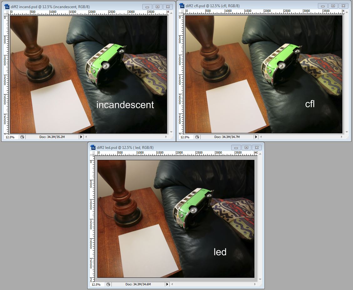 These are the test pictures captured in a screenshot of Photoshop. You can click any picture in this blog to enlarge it.
The pictures are reasonably similar. The camera being on AUTO adjusts the brightness level of the scene to produce a "better" picture but I was happy to let it do that. What is not so apparent in the images is that my own perception of the scene was that the led was slightly less bright than the other two. What I was not able to do was to measure with a light meter. I have only what is built in to the camera.
 This closeup of the same pictures shows the color shift in the blue/green turquoise or whatever color the bus is? I remember many years ago trying to match a similar colored woman's wedding dress and the editing suite would just not co-operate. Something about mixed lighting sources at the venue causing the electronics to be fooled as to the color. To do this properly, I would first white balance the camera on the white sheet of paper and then refocus on the scene with the color corrected.
But in terms of this simple test, it is apparent that the brightness from the led is more than adequate for detailed pictures and probably a great reading light.
The color from the led is slightly different from that of the other two. IKEA calls the LEDARE bulb "opal white". Is that like "cool white"? I did a search on "opal white" but the term seems to refer to a frosted white, not a color, similar to the opal mineral.
I checked temperatures of the three bulbs with an infrared thermometer after each had operated for at least 10 minutes.
| TYPE | TEMP F |
| Incandescent | 160 |
| CFL | 145 |
| LED | 96 |
Clearly a significant amount of the energy going into both the incandescent and the cfl is being wasted as heat. The led is positively cool by comparison.
Finally I measured the energy consumed by each of the bulbs using a "Kill-a-Watt" meter.
| TYPE | Consumption W |
| Incandescent | 55 |
| CFL | 12 |
| LED | 7 |
 The voltage input to the lamps during this test (as read from the Kill-a-Watt meter) was 125 VAC.
So the led uses much less energy than an incandescent but not that much less than a cfl. Still, the reduction from incandescent is truly significant and the led overcomes some of the cfl's weaknesses, such as poor cold weather starting and led do not use mercury (but they use other stuff).
A less technical reader might find the look inside the bulb that follows to be interesting but not essential.
The last part of my exploration involved answering whether both phases of the AC power input were being used for best efficiency and whether there was a fuse. Since I had already packed my current probe for the move I could not look at the input current directly. So I decided that opening the bulb to look at the circuit might help me to answer both questions plus have a look at how the bulb was constructed. This would destroy the bulb and make it unusable. Done in "the interest of Science".
Do not try this at home - use caution if you do!
 This is the business end of the IKEA LEDARE with the plastic dome removed. Nicely done circuit and construction. The bulb housing from here down is aluminum which is necessary for heat dissipation, to keep the electronics below some maximum temperature.
Notice the pattern of pinholes around each LED? The manufacturer is using copper plated-through holes to increase the thermal coupling to the aluminum housing below. The circuitry in this led lamp is less heat tolerant (cannot go to as high a temperature) than a cfl which is constructed typically with a ceramic housing.
This led lamp is the heaviest of the three due to the mass of aluminum used. Good recycling potential. Leds should last a long time but when this one dies, it gives up a nice aluminum ingot.
The leds themselves are the six small yellow tinted rectangles. You will notice that three (D2,D4 and D6) are a different yellow color than the other three. Yellow/orange indicates the use of a color shifting phosphor in light path of the led. Light is made at one frequency naturally by the led junction and is converted or shifted to another frequency (color) by the phosphor. That two different phosphors are being used shows that there will be a blending of two different light groups or spectra, probably in an effort to smooth the total light output. The yellow orange color is not the color of the light that is produced.
I think we've seen that this led lamp needs some blue but I will do some more work on that.
It is difficult to see but the leds seem to be all wired in parallel - which is a surprise. Leds must be fed a current limited diet and this is difficult to do well in parallel unless the leds are very carefully matched. Otherwise one or more will "hog" current at the expense of the others. Usually leds are wired in series or series parallel.
 Here are two views (top and bottom) of the drive circuit which was inside the aluminum housing. The yellow and white wires at the left were soldered to the led circuit board so these are the "output". The resistor (component loose at one end with colored stripes) was connected to the center pole of the base so this is the hot "input". One wire is missing, still attached to the base outer screw shell that was connected (soldered) at the point just below the yellow elipse at the point labelled "B". This is the neutral "input".
I have not analyzed the circuit but I think that I can answer the two questions which brought me this far.
The resistor is the fuse. It is directly in line with the input and has a very low value. I haven't tried to measure but from the color code of the stripes, I would say that it is a 1 ohm resistor. Not the best fuse in the world and certainly not easily replaceable. But no-one will be replacing these fuses I think!
The component in the yellow shaded circle appears to be a full wave bridge rectifier which means that designer is using both phases of the electrical current. With some AC operated leds, this is not so, like with string lights where the lights are only on half of the time. Using the full cycle is twice as efficient.
I am not trying to reverse engineer your circuit Mr IKEA but merely trying to understand what you have done from a diy perspective.
These IKEA LEDARE bulbs are promising. I will have to go back for a few more.
Thanks for your interest.
George Plhak


