Showing posts with label misc. Show all posts

Wednesday, April 06, 2022

CO2 meters

Remarks on some of the inexpensive CO2 meters I am testing.

Showing CO2 readings from 5 meters in my office. My own breath over a few hours while in a smallish 10x10ft office room with one door open to the rest of the house. Only me in the house (plus a cat).

I had hoped the initial results would be more similar but I do see them converging with time.

[click the picture to enlarge]

The cat and I emit CO2 constantly and we move around the house so the meters fluctuate. There are some tiny seedling plants in the house but probably insignificant CO2 sinks so far so our household CO2 should be reasonably steady. Other gases should not cause deviations. The meters should be specific to CO2 but I've found that the cheaper meters react to other gases.

Please note the range from 623 to 795 (CO2 parts per million), even among these "better" units.

One hour later the average rose to "around 800ppm" where it remained more or less for the day.

800ppm is a NOT a serious level of CO2 in my home but it is worth it to know the relative level.

The meter readings track together but there is a lot of variation. The meters update at different intervals. If I took the same picture 10 times, all would be slightly different. Digital makes one crazy with apparent precision.

I did learn that the CO2 detector inside the meter should be a NDIR (Non Dispersive Infrared) type sensor specifically to be at all useful. The price of NDIR units is typically $50+ (and up to $800 or more).

These are all NDIR meters. The most expensive of mine so far cost about C$200.

In the morning when I first enter the office, the meters will typically show "around 400ppm".  Home heating is on and windows are closed (Canada winter household conditions).

These meters are Li-Ion battery powered and will run for about 6-8 hours or continuously if plugged in via USB. They work great in the car or in your pocket or on the meeting room table.

If I leave a CO2 meter outside (or in my garage) some will read down to 350ppm at times. That is the background CO2 level here which is going up with time but is difficult to measure. Interestingly some of these meters will not read or display below 400ppm at all.

Some NDIR meters will do an automatic baseline (ABC) calibrate function to eliminate the effect of drift. You need to leave them in place for while (days or weeks to stabilize then move them outside for a time occasionally) or follow the hopefully provided calibrate instructions.

Cheaper meters do not use NDIR sensors and are only so-so with CO2. They do not discriminate well other volatile organic compounds (VOC's) like cooking vapours, alcohol or cleaning agents so will show high values sporadically. The cheap meters will drive you crazy with false results. I have about 20 of them.

CO2 meters will also typically show temperature and humidity which are not necessary, related or required for a CO2 measurement. The temperature/humidity are separate inexpensive sensors inside the unit, separate from the CO2 sensor..

More measurement types (3in 1, 5in1 or even 6in1) are not necessarily better than one good CO2 measurement.

Please see my earlier article about the meter at lower right (HT2000).

More soon.

Postscipt Apr 4 2022

Same setup a couple of days later.

I notice that the meters now typically cluster within 75-100 ppm of one another.

It seems that they have become accustomed to the room or each other or perhaps the autocalibrate is having an effect over time.


Thank you for your interest.

George Plhak
Lions Head, Ontario, Canada 

Wednesday, August 11, 2021

polishing headlights

Improving 14 year old headlights for about $25 and a few hours easy work. 

Most of the time is to allow drying after each step.

I used 1000, 2000 then 3000 grit 2 inch sanding disks in a drill to wet sand, followed by hand sanding then washing and drying at each step. Then I put on gloves and applied Wipe-New.

I had not used Wipe-New" before. The result is impressive.

The "AFTER" picture
<click to enlarge>


The "BEFORE" picture

The headlight as it was with masking tape applied to the surrounding paint.

Hard to believe it was this bad.

Three steps of progressively finer sanding disks were used wet followed by cleaning and drying after each.

Machine sanding with the drill was followed with hand sanding with the same grade pad at each step.

New sanding disks were used for each headlamp at each step.


Wipe-New back of package

Contains:
tert-butyl acetate,
1-choro-4-(trifloromethyl)
benzene and benzaldehyde.
Wear gloves.
Use outside.

Have both headlights prepared before you open this package. It evaporates very quickly.
Wipe each headlight only once to coat the surface.
I went in horizontal strips.
The applicator works well.
Do not try to touch up.
Wait for an hour.


Wipe-New package

Wipe-New product link

I bought at Canadian Tire for about C$20 +tax


    The live action "TECHNIQUE" video
 
The final result.

I am very pleased!

I will see better in the dark and will not confuse on-coming drivers.
Thanks for your interest.

George Plhak
Lions Head, Ontario, Canada


Tuesday, June 22, 2021

fixing old stuff

Troubleshooting two big old Tektronix 7854 in my garage. The first analog oscilloscope with a computer. An oscilloscope lets you "see" electricity.
 
Currently I am checking the LV power supplies. I think I can operate them completely out of the scope.
 
I hope it will be an advantage to be able to compare one scope to the other. I have already found a few things
 
I have the 3" thick paper Tek manual with beautiful foldout diagrams and all the update pages (late issue).
 
And I have a third working 7854 on a cart in the house. I can always open that one up too :)
 
Why do this?
 
These scopes might be forty years old. A modern $400 oscilloscope from China does more, better, smaller, lighter, and is way cheaper (but probably not with 400MHz bandwidth).
 
The 7854 was introduced in 1981 at a base cost of US$10,500. In my 1987 Tek catalog it lists for $16,220 but by then included the waveform calculator and the extra memory option. Project Leader on this scope was Tom Rousseau. More about Tom and the 7A26 amplifier.
 
 
Thanks for your interest.
 
George Plhak
Lions Head, Ontario, Canada


Wednesday, May 19, 2021

easy change


John Deere Easy Change oil system

Today I tried to change the "Easy Change" oil filter on my cute little John Deere E120 lawn tractor. I am supposed to easily remove a canister that contains the filter and about a third of the engine oil and replace with a fresh unit. No need to drain the oil, they say. Cost locally at Home Despot is C$70. They call it Easy Change. First time I have tried it. It was anything but easy.
 
Normally, an oil and filter change takes about a hour if done carefully and costs about $20 with good quality oil and filter. Virtually all of the engine oil gets replaced with new, not just a portion.
 
But I am stuck. The old canister came off with some effort. Push and turn counterclockwise they say. Difficult to remove but it seemed to come off OK.
 
The new filter did not lock into position as it should. It is in the middle and it is really stuck. There was a click but I cannot remove it or force it to the fully locked position
 
In a conversation this morning with my local JD dealer 1 hour away they say "put the tractor on your trailer and bring it in. We will get it off for you while you wait". Thanks. I don't have a trailer.
 
<more conversation with the dealer>
 
I am going there tomorrow to get the parts to remove the "Easy Change" oil filter system and replace with a conventional filter and drain port.
 
JD equipment with an Easy Change oil system can be fixed. 
 
It is a bad idea that can be retrofitted for less than the cost of one canister.
 
Big Thanks to <my local JD dealer> for help.
 
Thanks for your interest.

George Plhak
Lions Head, Ontario, Canada


Wednesday, March 11, 2020

battery testing 3

Retesting after 6 months of daily use shows ~10% decline in capacity of my 18650 lithium rechargeable cells.

Last summer I tested three new 2200mAh cells. Initial average capacity was about 2030 mAh with my test which may or may not be accurate. After six months in service, I repeated the test with the same tester and method and found average cell capacity was now about 1822 mAh, or a reduction in capacity of about 10%. Raw data is here.

I attribute the reduction in capacity to my daily usage of the batteries although there could be other causes (* below).

The squiggle (~ tilde) before the 10 means "about" and that is really the theme of this post. Often in amateur science and engineering we need an approximate answer to check a hypothesis or opinion. Some quick measurements, even if approximate, are better than no data at all. Hence the "about". Sometimes repeatability and consistency may be more important than absolute accuracy when we are trying to compare.

In the case of these batteries I had tested for capacity about six months ago. Since then I had used these batteries daily in a vape pipe. They seemed to be performing well. Typically I would switch a battery sometime mid-day putting the partially discharged battery back onto the charger and inserting one of the two other charged batteries into the pipe. So I knew two of the three batteries went through some sort of discharge/charge cycle daily determined by my vaping habit with was pretty steady during the six months. I tried to randomize which battery I did not use each day but wasn't entirely careful about that aspect.

Since I had not used these PKCELL 2200mAh batteries before, I was curious if there was an effect on battery capacity and how much it might be.

Why go to the trouble of testing? I paid about Cdn$15 each for these cells. Some have been junk. I am accumulating things which use 18650 cells and had other applications in mind so I will need to buy more. The best way to determine capacity is to measure with a controlled test.

Initially I had tested each battery three times. Three data points. I like three. With only two measurements, if something goes wrong or varies, it may not be apparent in the data. The two measurements will differ always. With three measurements, hopefully two will be more similar than the one which varied. Ideally all three would cluster tightly. More measurements would be even better but we are after an approximate answer so three is good.

I tested with the same ZHIYU ZB2L3 v2.3a tester and the same 7.5 ohm resistor.

There is a new version 3 of the tester which I have ordered.

[click any pic to enlarge]

I considered changing the load resistor. I am simply using one of the two resistors that came with the kit. Readers will notice that I changed the arrangement of the load for the second round of testing with auto batteries to create a heavier load. I'd like to more closely match the 1C rate that the manufacturer has used for determining the branded 2200mAh rate. But at this point that is less important to me than using the same test and load to compare batteries from different manufacturers or different batches from the same company.

I have recently done initial testing of two new batches of 18650 batteries: four more of the PKCELL 2200mAh and two bright pink Samsung cells, the best I've tested so far! All tests with three repeats each.

Thank you for your interest.

George Plhak
Lions Head, Ontario, Canada

* Other causes - I knew you'd ask. Hypothetical causes really, but possible. Like maybe the batteries have some manufacturing defect that causes them to loose capacity independent of charge/discharge? Or maybe I stored them in a hot car in the sun? I did not, with these batteries, but four similar cells are installed in two emergency flashlights in my cars. Not used at all but subject to some extremes in temperature. I might retest those cells another time.

[The next day] Another possibility why the measurements this time are lower. I had forgotten but was reminded by the photo I used above: I wrote that I was not happy with the battery holder and had ordered a different type. After the new holder arrived, I installed it with shorter, larger gauge wire as you can see in the pic. This is the tester and holder used for this series of tests, on the right.

So it is likely that the resistance of the output load circuit is now less particularly because of the shorter beefier wire. The holder contacts also look more substantial and are well soldered to the wires. Lower load resistance would increase current (the C rate) and reduce mAh measured. Would it be ~10%? I don't know. I should measure! That's the original battery holder and wires to the left.

I won't go back and retest with the thinner wire. But when I retest the latest cells, I will be comparing them to the results from this tester. That's the importance of consistency.


As is my custom, this is not a paid review nor do I receive or solicit any product in return for writing. I am not selling these products. Just ideas. I don't get a commission. I don't show ads. I don't have a fundraising or patreon page.
I write in the hope that this is interesting or useful to you.
If you would like to show support for my independent work,
please consider commenting or buying one of my books? Thank you. George

Friday, February 28, 2020

solar printing


Markus Kayser - Solar Sinter Project from Markus Kayser on Vimeo.


Amazing.

I wonder if finely shredded plastic waste could be used instead of sand to make fused plastic works?

Fresnel lenses are pretty cool.

Thanks for your interest.

George Plhak
Lions Head, Ontario, Canada

Friday, September 27, 2019

battery testing 2

Using the small automatic tester to check car sized batteries takes much longer but gives useful sorting information.

Continuing with the theme of battery testing but on a different scale, I have changed the loading of the battery tester to draw more current. The three large resistors are in series across the load terminals of the tester. The resistors are the three rectangles with my handwriting on them.

[click any pic to enlarge]

The handwriting is the measured resistance in ohms. Since the resistors are in series, the three total 15.7 ohms. Each are rated at 22 watts so the three theoretically could dissipate over 60 watts. With only 12 watts used in this test, the resistors get very hot, too hot to touch, hot enough to boil water. The metal screen helps to cool them.

I would first charge the battery fully with a separate charger and let it rest overnight. A good battery would measure in the range of 12.4 to 12.8 volts. The tester was then set to discharge the battery to 11 volts and the test started.

The tester checks the battery voltage and offers to start with a default of 10.5 volts but I did not want to discharge the batteries that low.

With a freshly charged battery the current drawn at the start of the test is about 850 milliamps (0.85 amp), or about 12 watts. This is a modest rate for a car battery. The tester is specd at a maximum current of 3 amps so this is well within its range. A load of 12 watts might simulate one charging cell phone for example or a bright LED light.

The test takes some time. I managed to check four batteries in the past couple weeks including an almost dead battery that was then returned for recycling.

I expected this battery to test weak. It had been removed from my car three years ago. It would start the car ok in the summer but was not reliable in the winter. This particular battery had continued in service here in a small solar UPS in the shop and true to form, it would last only one night in the dead of winter powering a 12 watt LED overnight. If it was cloudy the next day, the LED would not last till morning.

This battery took almost 14 hours to discharge to 11 volts and gave a result of 10.3 amp hours. I charged it again, repeated the discharge test and got 10.7. So there was some indication of repeatability to the test.

The new battery I purchased (the one in the first picture) is now installed in my car. As expected, the factory fresh battery scored well at 54.5 amp hours. It took three days to discharge!

So I now had a range for good to bad.

Continuing with three other lead acid batteries, I managed to get clear, unambiguous ratings of the battery capacities, all at the same rate.

The "old" battery that I just just removed from my car will now go to the UPS. It tested 37.2 AH.

Video is here.

Thanks for your interest.

George Plhak
Lions Head, Ontario, Canada

[update Oct 6] Great comment from Len Warner:
This is very sensible testing but one should not deep discharge automotive batteries unless there is a real need to know. However, all this seems valid: new battery tested to establish a reference; replaced car battery tested to qualify it for ups; and old ups battery tested to confirm it's ready to scrap. But the other two tests have cost you a cycle life.
Another test you haven't done is charge retention: ancient automotive batteries tend to have lost plate material, which accumulates at the bottom of each cell and shorts it out so the battery won't hold its charge long-term. It also tends to affect cells unequally, leading to cell imbalance and overcharging.
Traction batteries and leisure batteries should be more resistant to deep-cycling because of stronger plates and sumps for debris.

Tuesday, September 24, 2019

visitors

Hello!

I am humbled and grateful for your interest. And for your comments!

Each day is different. This chart is today. Usually I have more visitors from Canada.


The data is page views by country over the past 24 hours.

[click pics to enlarge]

Most often Google brings you here or you've clicked a web link. You stay to read, on average, for almost two and a half minutes!

The "bounce rate" for this site is very low, which is good. This shows that my readers stick around to read more.

Please know that I appreciate your visit!


Thank you for your interest.

George Plhak
Lions Head, Ontario, Canada

Tuesday, September 03, 2019

digital clock


Some additional detail. A short photo essay to expand on the above FB post. [the FB link does not seem to be fully live. Try this instead]

The circuit working on my bench yesterday. Link to the video. It keeps time from the 60Hz line frequency so it is pretty accurate unless the power goes off in which case it needs to be reset. It doesn't know about daylight savings time. It does not dim at night. It's big and heavy. But still pretty cool to watch.

In the very early 70s, while a student at UofToronto, I found giant neon nixie tubes at a surplus shop in the electronics market then around Yonge and Wellesley.

I was told those tubes came from the stock market display board at the TSE (now the TSX). The display tubes for this vital board were changed regularly and these were the rejects. I think they were expensive, maybe $5 each?. I was a student so couldn't afford new ones then. In the 80s, I replaced those tubes with these real NEW ones that were still available then, about $30 each. Advertised on EBay now for US$200 each for USED ones.

Digital clocks were a very hot item then and there just weren't any BIG Digital Grandfather Clocks, so I decided to build one. Because of the used tubes, this is a reuse project!

The presentation needed to be impressive so I enlisted the help of a friend who was a better woodworker. He helped me with the cabinets made from mahogany (which you could buy then) and a huge sheet of 1/4 inch smoked plexiglass. Until yesterday this clock was almost six feet tall and very heavy and awkward. It was not very stable on a floor but it never fell over! It did not have levelers at the bottom so needed shims to be vertical on a old slanted floor.

I had moved this clock wherever I went for the past 45 years. I moved it maybe ten times. It was coming apart at the bottom and needed to be fixed.

The big space under the clock was intended to house an electronic pendulum which never got built. Nor the electronic chimes. So there was really not the need for the big space. Yesterday I shortened the cabinet and made some repairs and improvements. Now it fits on a desktop or shelf.

Built with six fancy Burroughs special 17 pin sockets, hand wired and supported with a piece of wood.

The bottom of the clock board.

Mains power supply. The nixie tubes need 180 volts. The rest of the circuit used low voltage. This made both. I cannot believe it worked for 45 years!

The board layout.

Then in 1976 Heathkit introduced a digital floor clock GC-1195 and digital shelf clock GC-1197. The first commercially available digital "grandfather" clock. Popular but not a huge success.

Their display used wedge based incandescent lamps that burned out frequently. Heathkit offered a Winchester chimes option. No pendulum.


I got busy with school and never made another clock.

Thanks for your interest

George Plhak
Lions Head, Ontario, Canada


Wednesday, August 28, 2019

battery testing

Some of my lithium rechargeable cells weren't lasting as long as others.

Sorting my batteries was made easier with a simple inexpensive battery capacity tester.


I found a wide variation in my own assortment of various 18650 Li-Ion cells. Now each cell has a number, the milliampere-hours (mAh) the battery achieved on the tester.

[click any pic to enlarge]

The one pictured had been running on the tester for over an hour. At the time of the picture, that 2600mAh battery had achieved 1716mAh (the display shows amp-hours ie 1.716 Ah). The final capacity is determined automatically by the tester when the battery voltage falls below 3 volts, the test is stopped and the final Ah shows flashing on the display. For this battery, the final was 2.758 Ah (2758 mAh).

This one battery is my BEST battery and the ONLY one that achieved a result on my tester greater than what was branded. None of the rest achieved branded capacity out of 15 cells tested. Bought from various sources, my 18650's cost me between C$7 to $15 each.

The better ones are going to be used more often in my flashlights and USB power packs. The weak ones are going to help guide my purchasing decisions after they go to electronics re-cycling.

I am using the ZHIYU ZB2L3. Mine came from Banggood product ID: 1112859 in a little over a week after I ordered. The units I received were v2.3a.

ZB2L3 is a small circuit board which discharges a test battery into a resistor while measuring battery voltage and the current delivered to the resistor. ZB2L3 calculates the mAh. While testing, the display cycles three numbers and an LED at the side of the display shows alternately amp-hours, amps and volts. You can see a video here.

The micro USB cable only supplies 5 volts to the ZB2L3, not data. Since this is a complete discharge test, the ZB2L3 must have an alternate source of power hence the USB connection. Almost no energy is drawn from the USB. You can plug it into any USB charger or port. It will not charge the battery.

There is no data analysis available from the ZB2L3 other than from the display. I'd love to know that there was a way to capture a discharge curve such as this one, to explore different discharge rates and temperatures.

Two power resistors came with my ZB2L3. I used only one for all of this first round of tests. By using one of the supplied 7.5 ohm 5 watt resistors, the battery at 3.7 volts was seeing about a half amp of draw. This is (3.7X0.5=) 1.8 watts which makes the little square 5 watt resistor very hot, too hot to touch. That is why I have a cardboard sheet under the test, to protect the desktop. In hindsight it should have been a fire-proof insulating sheet. The battery gets slightly warm as it's working pretty hard.

I got the 18650 size battery holders from Banggood also. These I won't recommend. Although the battery should be held firmly against the contacts, with these battery holders it is difficult to remove the battery. The wires are very flimsy and probably contribute some voltage drop to the battery voltage measurement. Wires to the battery should as short as possible and a larger gauge wire. The contacts in this holder probably wouldn't handle soldering well. I will order better holders.

This test is a vivid demonstration of how much energy is stored in these little cells. The resistor is too hot to touch for several hours.

The ZB2L3 can be used for a range of batteries up to 12 volts and measures up to 9999 Ah. The value of the resistor can be adjusted to change the discharge rate up to 3 amps maximum but you must keep safety in mind of course.

Thanks for your interest,

George Plhak
Lions Head, Ontario, Canada

These cells, branded Ultrafire 6800 mAh show that the test gives consistent results on one type although the value is way lower than the branded capacity?!

The battery flipped over to show the branded capacity tested at only 795 mAh, the lowest of this batch of "6800 mAh" batteries.


As is my custom, this is not a paid review nor do I receive or solicit any product in return for writing. I am not selling these products. Just ideas. I don't get a commission. I don't show ads. I don't have a fundraising or patreon page.
I write in the hope that this is interesting or useful to you.
If you would like to show support for my independent work,
please consider commenting or buying one of my books? Thank you. George

Tuesday, July 02, 2019

improving cell data with a refrigerator

I have been experimenting with my cell phone as the hot spot for my home internet. The pic is my Rogers cell based internet after placing my phone in the best location which I discovered here yesterday, on a box on top of my fridge.

Rogers is offering an unlimited data plan which was a $5/mo upgrade so I took it. I intend to drop my land line based internet to save by having cell only.


My current ADSL (phone line based) internet is the least expensive plan from the only landline provider in my area, Eastlink. I enjoy slow but solid internet, 5 Mbps download, 1 Mbps upload, unlimited for $75/mo. Rogers will now cost me $80/month for their cheapest wireless unlimited plan. (see their website and the pic above)

Before yesterday, my Rogers cell data and reception were not good inside the house. And highly variable, from un-usable to outstanding. Today, reception has not changed except that I found the best location from which to access my available signal. I am pleased with what I found but there are a couple of caveats (read on).

Where I live has two negatives for cell data. My house is low in elevation relative to the two area cell towers so much of the cell signal is blocked by surrounding hills. Second, my house is covered with a metal mesh based cement that effectively shields electromagnetic radiation, like cell signals. Two negatives.

I looked at 4G cell repeaters/boosters. Hundreds of dollars and not all work with Rogers. I haven't tried one yet.

I learned about cellular booster reflectors from old satellite dishes.

Instead, I loaded an app to measure cell signal strength. I am using Network Cell Info Lite. This one is for Android.

The gauge display shows main and next best cell signal strength in dBm. The gauge updates every second or so.

Most people don't think much about where they put down their phone. Maybe you carry yours? Our phones are marvelous little radios which are sensitive to orientation and surroundings! Especially when we need them to work their best.

I have been exploring my house for my BEST signal. Signal inside my house varies over a huge range from -100dBm to -125dBm. The dBm scale is logarithmic. Lower numbers in this case are hugely better.

I can see that I am using band 12. This changes sometimes to band 4. Both of these are 800-900 Mhz. In rural areas like mine, lower frequencies like these will travel further and have adequate data rates to impress me when working well!

I don't get to pick a tower or frequency. Those are selected auto-magically between my phone and my provider.

I can see LTE on the display. This might mean 4G but it's complicated in Canada.

Yesterday I drove to the two towers that serve my area. look up your local cell towers, operators and frequencies Each is about 6 km distant, one is to the north and one is south. Using my app phone signal strength meter I measured the signal about 1 km from the towers at about -60dBm! But nobody lives there, well not many anyway...

By clicking once on a tower in the map, I learn that at the northern tower, Rogers uses 700MHz, 850 MHz and 1900MHz, Bell uses 700 and 850. At the southern tower, Rogers uses only 700 and 850. Bell is not on the southern tower. More specific information on all of the cell transceivers at a tower comes up in a table if you double click on that tower.

Back at my house, quite by accident, I found TWO spots where the signal is best. Both are on top of large grounded metal objects: my refrigerator and my clothes dryer. The metal case of both appliances is attached through their electrical cords to earth ground.

With my phone flat directly on top center of either the fridge or the dryer, my signal strength is the best inside my house. The fridge is slightly better at -97dBm.

When I check download data rate using speedtest.net from either of those spots, it is noticeably higher (twice as high!) than most anywhere else in the house!

But Upload data rate is much worse when the phone is placed directly on top of these large metal objects! It slows to less than 1 Mbps. But - if I lift the phone up about 5 inches high and place it on an empty cardboard box (about 1/4 wavelength, my phone is using 850MHz) the download data is still good and the upload data improves enormously!

Is it possible that the appliances are making a ground plane for the phone, helping with receive and transmit?

I tried different height boxes (two, three, five and eight) and the five inch seemed to be best.

I tried changing the phone's orientation, on either side, on the ends, rotating it slowly in different planes while holding it approximately 5 inches above the fridge and trying to watch the display. But placed down flat on the phone's back on the 5 inch box seemed the best (lowest) dBm reading. Minor changes if rotated slightly and slowly on the box.

I tried putting the phone over a large un-grounded metal plate on the kitchen table, with and without the 5" cardboard spacer box. The metal plate made no difference.

I rarely use my phone for voice so parking it on top of a box on the fridge is no problem for me. I can hear it ring anywhere in the house.

When I go out, the phone comes with me so the home network stops. I don't have any "smart home" devices that need always internet so this is not a problem.

If there were two phones in the house, one could set up sharing of two cell links with two hot spots (with bridging?) to further improve data rate?

If you try this, please let me know.

This experience has caused me to clean the top of the fridge. It was pretty dirty up there but cleaning had no effect on the signal strength.

Thanks for your interest.

George Plhak
Lions Head, Ontario, Canada

Update Jul 22 2019 Eastlink has been OFF since I wrote this and I have been accessing the web with Rogers cell only. I frankly haven't noticed the change, except for generally better responsiveness (plus!) and having to retrieve my cell phone off the fridge when I go out and then putting it back (negative). The actual internet data service is far superior to what I was getting with Eastlink (5mbs down 1 mps up) as this speedtest just now shows. I was worried about the throttling back "feature" but that does not seem to have happened yet. I get my latest full Rogers bill with usage and dollars on the new plan tomorrow.

Monday, June 24, 2019

hot wire foam cutter

I built a simple hot wire foam cutter to make parts for a couple of projects.

I wanted to slit a full sheet of 1.5 inch insulating foam into strips for a mooney wall. Another project, a water heater insulator, required large foam discs.

What started as quick and dirty ended up a very useful tool.


Using scrap wood, I began by adding a slot and a "fence" to a partial sheet of particleboard to make the table. The board was what I had, about 3 foot by six foot supported on two saw horses. I added a strip of wood lengthwise opposite the fence to support the front edge. The table is hung on the wall when not in use. [click any pic to enlarge]

Using particle board was problematic. When fed across the table, large pieces of foam would catch on the tiny sharp fibers sticking out of the particleboard. I later sanded and painted the top surface with several coats of latex paint which helped. It would have been better to use a smoother surfaced board.

The cutter arm is U shaped to support the cutter wire and slides in a groove under the table to adjust. It is then fixed in place for the cut.

I thought to make a variation with the hot wire slide-able to make cross cuts but haven't done that yet.

The slotted hole in the table is for the hot wire. I didn't want to cut through the fence on the back of the table. There is a minimum width that the wire can be set to, about 6 inches and a maximum of about 18 inches. The width of the slots for the mooney wall are 14.5 inches so this is a good amount of adjustment. Varying the dimensions could give other capacities.

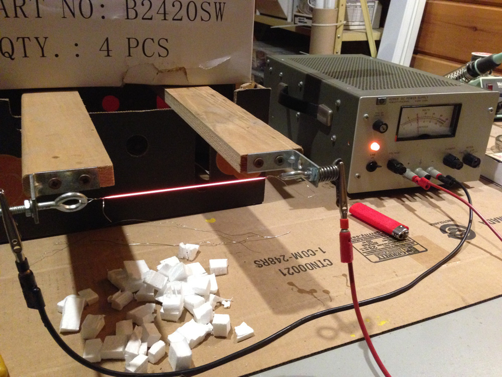
The hot wire on the bench with power supply testing cutting action!

It turns out that the wire does not need to be red hot as shown, but just slightly less, sort of a dull red. I have an adjustable DC supply giving the wire about 4 amps at 8 volts. The voltage and current will depend on the wire type, gauge, length and the desired temperature so the adjustable lab supply is a good fit for a hot wire cutter. Normally the supply sits under the table and is connected to the two ends of the hot wire with test leads.

The wire I am using is heater wire (nichrome), typically used in toaster ovens. The first samples of wire I used were harvested from an old appliance. Later I found that I could easily buy small amounts of nichrome wire on Ebay from China so ordered 0.3, 0.4 and 0.5 mm coils.

I found that 0.4mm nichrome gave good cutting life and resistance to breaking. Getting the right temperature and the feed rate requires a bit of experimentation.

Nichrome wire expands when heated, as much as 5%, so there is a spring in the mount to put the wire under tension. When at the operating temperature, there should still be a bit of tension from the spring to get a straight cut.

The wire is simply looped through the eye bolt and wound around itself a few turns. The nuts on the eye bolts are adjusted to put the wire under tension. Normally I form, adjust and test the wire on the bench out in the open, then remove it from the arm, mount the arm on the table and then remount the wire through the slot in the table. It's easier.

Shows the smooth cut on blue type styrofoam. The edge obtained is very smooth.

Cutting foam discs with a pin through the center into the table as a pivot.

Using a thin template to guide the wire to produce a cutout in one of the discs.

Again using a template to make cutouts in one of the discs which has been already cut in half with the wire.

One of the many eight foot by 14.5 inch slabs for the mooney wall that was cut with the wire cutter.


Thanks for your interest.

George Plhak
Lions Head, Ontario, Canada

Detail under the table showing the mount for the arm made from scrap wood. The arm (with the wire removed) is inserted in a slot from the back and fixed in place with the screws that protrude to the right. Crude but adequate.

Wednesday, May 29, 2019

rain barrels 2

Barrel equalization with a siphon bridge and flood control continued

rain barrels part 1


Lessons learned: This is a former rain barrel setup where I had re-used three food grade barrels on a raised platform behind a pool shed/pump house. The location was ideal, steps away from a large (5m x 10m) vegetable garden. The edge of my solar pool heater array can be seen at left back.

Using only rain water my three barrels were adequate to spot-water my garden over several hot summers without diverting the pool waste water. I used a watering can, not a hose. Better exercise and water control.

The two downspouts delivered all the rain water from the shed roof into the outer barrels.

I considered diverting some of the waste water from cleaning the pool sand filter (the single white pipe lower right) into the barrels. The high flow rate of the waste water made it difficult. I had once measured the flow rate as 37 gallons per minute. There was no "low" setting for the pump and 50000 gallons of water available in the pool. Better to just let it blast out into the seasonal stream. The wastewater pipe extended about 5 meters from the shed toward the stream.

So diversion of the pool waste water was not really required. But some of the details of that system could have been improved.

Covers on the barrels prevented insects from entering and laying eggs (like mosquitoes). Some designs have a screen at the top of the barrel. Any debris from the roof would have to be cleared regularly from this screen. That sounded like a bad idea.

Here, rainfall via the downspouts dropped straight into the barrels through tight seals in the covers, keeping insects out. But was not a good idea for a couple of reasons.

Any debris from the roof went directly into the barrels. By the end of the season, there was a thick bed in the bottom of the outer barrels, enough to clog the equalizer hoses.

There was no provision for overflow. During torrential rain a small lake would form at the back of the pool shed from the water that overflowed the barrels. Next to the house this might cause water to enter the basement or saturate the foundation. But behind the pool shed this wasn't a serious problem.

The single tap was on the center barrel. I had used a fancy and expensive bulkhead valve from Lee Valley Tools, so there was only one tap from which to draw water from three barrels.

I needed a way for the water to flow between the barrels, as new water was added to the outside or as I took water from the center tap. You can see my solution in this picture [click any pic to enlarge]. I used Carlon electrical fittings and short lengths of garden hose to connect the three barrels at about the same level as the tap. The tap height establishes the lowest level that the water can be in the barrels so the equalizing hose should be at the same level so all three tanks drain equally.

If the equalizer hoses or the tap are up on the barrel somewhere, not at the bottom, you won't be making full use of your barrel capacity.

A barrel should be raised off the ground, at least as high as the top of your watering can, or higher.

Back to here and now: I have re-arranged my two 55 gal re-cycled food grade barrels to be at one end of the roof rather than one at each end. I want to do some work on the other end of the wall so that barrel had to be moved. I have adjusted the trough on the roof edge to slope downward to this corner rather than down from the center so all the water now flows to this corner.

I have a single diverter (at the green arrow - the Canadian made "Catch-A-Raindrop" described in part 1) in the downspout to the ground and a single fill pipe to the left barrel. The downspout sends overflow into a drainage ditch to get the water further from the foundation. The diverter will not send water into the barrel when it is full. Leaves and debris from the roof continue to the ditch. It works great!

But it only feeds one barrel while maintaining auto shutoff to prevent overflow.

I needed a way to equalize the level in two barrels. I could have used the same arrangement as I did above but instead I decided to try a siphon bridge.

My siphon bridge is a length of hose which reaches the bottoms of both barrels. Primed with water (no air inside) the siphon bridge will allow water to flow from the barrel with higher water level into the barrel less full. I am using PEX.

Here I am demonstrating to myself that the concept does indeed work. The right barrel had been about a foot lower in level. After about 1/2 hour, the two barrels equalized.

The siphon bridge was attractive because I didn't have to put any new holes in the barrels. I had already emptied, cleaned and refilled them. To accommodate the siphon bridge needed two pipe sized holes drilled in the barrel lids.

The final configuration with both barrels full and ready. The blue arrow shows the siphon bridge in place. The yellow arrows show the tips of the water level gauges.

Note that insects have no way to enter the water. The tops of the barrels are essentially sealed although some air can enter as water leaves the barrels.

I suppose the siphon bridge could be used to connect three or more barrels.

Although simple, the siphon bridge needs to be primed. This means sucking the air out. I used my mouth on one end, holding the other end deep in one barrel. I held it low to the ground to ensure that water was flowing at a good clip and then closed the end with my thumb and stuck it underwater in the other barrel.

It was necessary to have the PEX already inserted through the covers so they could be screwed down once the siphon was primed.

The siphon bridge has the disadvantage that it needs priming and it might again if it looses prime. The horizontal tube at the bottom approach does not require priming but it is more complex and needs more holes in the barrels.

rain barrels part 1

Interesting video of siphon bridge used between two raft beds.

Thanks for your interest.

George Plhak
Lions Head, Ontario, Canada

As before, not wanting to pick on Home Hardware. This is a current example of a popular rain barrel product with an insect screen at the top. Roof debris would clog this filter unless cleaned regularly. No overflow consideration. With tap at the bottom of the barrel you'd get more water out if the barrel was raised off the ground, at least as high as the watering can filler. Not sure how you would cascade two or more of these if you wanted more capacity.