Hello Carlos and thank you for your interest in my book. My answers are below:
On 12/14/2011 08:06 PM, carlos e wrote:
Hello Mr George,how you doing?
I see that you have a great job on this things,congratulations.
Thank you.
I brougth from you the plans to make my own unit...but I need to get some awnsers first.
Did you have some problem with acrilyc durabitity?
At first yes but it was a problem of my own causing. I let the concentrated light that was not properly focused at the collector tube hit the back of the sheet in front and the sheets were deformed by back heating. This damage occurred when the unit was OFF and not following the sun under control of the sensor. This was solved by painting the backs of the acrylic sheets white and when not using the array, parking it horizontally. The current acrylic is on the third year of use here. It needs a good cleaning in the spring, but it is fine. You can read more about that here: http://georgesworkshop.blogspot.com/2009/07/mirror-distortion-is-due-to-back.html
Did you tested some others interesting materials?
I did. In the book on page 30-33 I talk about MIRO IV polished aluminum, Galvanized steel (no joke), aluminum roof flashing, reflective film and acrylic mirror. I did not try polished stainless steel since I could not find it locally but others like this material. I would like to review the situation again since many different kind of materials can be used.
I am thinking about making some examples and sell it to some people but you know,I am a serious person I dont want to sell a bunch of problems to my friends..in case that they need to change the reflector in a short time!
I suggest you make one for yourself first to get experience and to adjust for local materials and situation. You should do your own life testing. Maybe your acrylic is different from mine but we don't know that until you use it for a while.
How long is your device working?
I started six years ago. The current "production" array which heats the swimming pool is essentially the same for three years. I am now replacing some worn parts and poor manufacturing (my own fault).
You did not refer in your plans,the size of your pool,how much litters or gallons do you heat with your unit?
Can you hit wich temperature increase in one day?
And about the ribs,do you think for example 10mm acrilyc it will be good to use instead of wood?
probably it will last more and no need to repair
I think it will depend on your conditions. Here there is winter cold (not good for most plastics) and wind but we do not get hurricanes, nor really heavy hail like they do in Texas. The wood highway sign material (MDO) is turning out to be very durable here but the edges must be sealed. The baltic plywood is my favorite, to be cut with a water-jet. But please try the acrylic. Check that it is UV stable. Use a lightweight material, like the wood laminate or plastic or you will be re-balancing the reflectors.
thank you so much.
ps. about mylar film can you share your experience with me too?
I did not use it. I thought it would be difficult to apply smoothly in small quantities and I was concerned about the durability. Others have used it with success. The manufacturer of Reflectech film recommends a purpose built "application machine" but I can't afford one of those nor could most of us, I thought.
Sorry if I am making a lot of questions but you seems to be a helpfull person and I really need your help!
My inglish is not very good,sorry for that...
Your English is GREAT! Thank you for your questions.
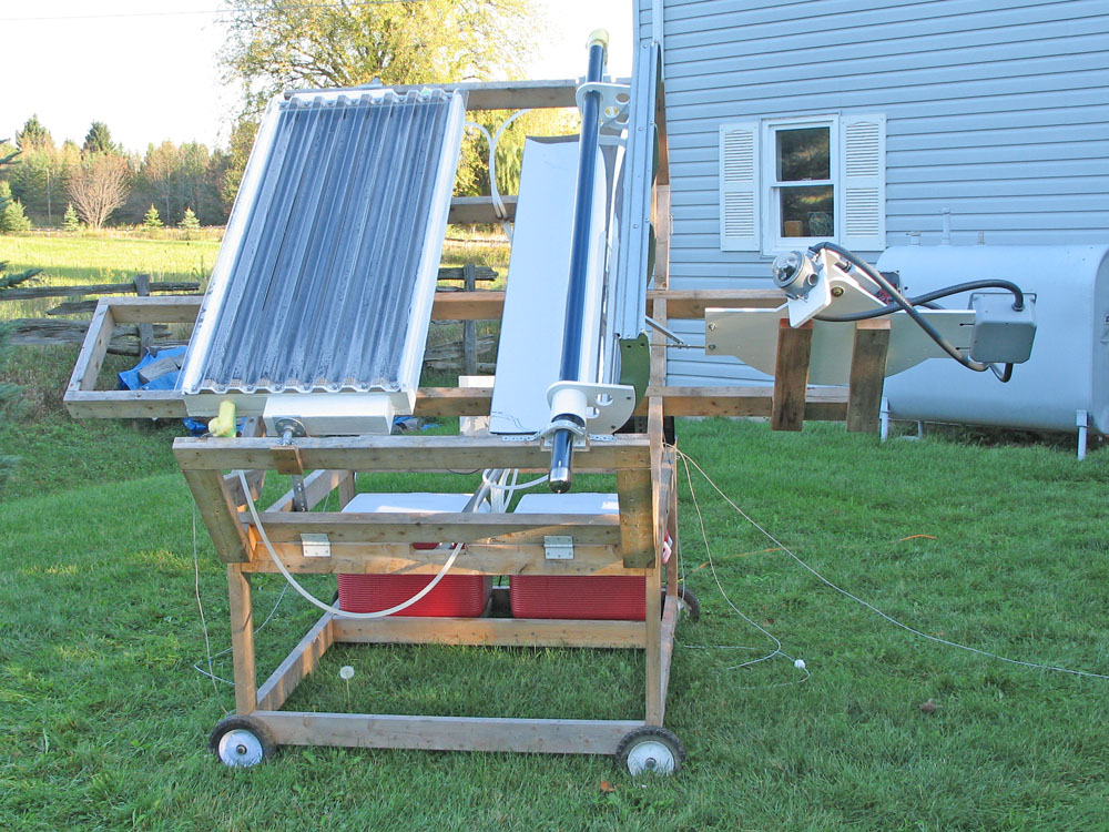
Two types of solar thermal collectors are in common use. The parabolic trough concentrator (example mounted on the right side of the solar test jig in the picture), is used in large thermal plants in the desert but is not often home built like the "flat plate" type collector (example at the left) which has avid user/builder groups promoting and advancing it's design and use.
Both make great Do It Yourself (DIY) projects that can be adapted to local needs. Both work well. How does their performance compare? I decided to find out. I was surprised that my two fairly carefully researched and constructed models were fairly close in performance. But there were some big differences.
Both types of collectors can be built by anyone who is handy with common shop tools. Most parts and materials are from home building supply centers. I used easy-to-follow plans from the internet. I built the collectors myself in my garage near Toronto and then did a series of measurements (See INDEX link below) to assess the heat gathered by each under the same conditions. Both types worked well. Both were challenging DIY projects. A solar heat source, even if home built, is a significant investment of time and dollars. For longevity and best performance, a project of other than the smallest size should be carefully done and perhaps a few models built to check concepts and presumptions. These are two of my models.
I am not yet attempting to make electricity. For now, I want to efficiently capture the sun's free heat and channel it into a flowing liquid - water in this case.
So which performs better: the flat plate or the concentrator?
As a DIY project, the result may depend on your building skills and perseverance but possibly more specifically on whether you choose to rotate your flat plate toward the sun with a tracker. This is more complex but it may be worthwhile. This is the only case where my flat plate out-performed my concentrator, but it was close, within a degree. In the other tests, the concentrator did better.
To be sure, the concentrator can have a real advantage in situations where a higher temperature is required. In this respect, it is better to choose the system with the higher stagnation temperature. Here the parabola truly shines. Over 636°F / 336°C reached in with the concentrator vs 200°F / 93°C with the flat plate (no flow). But with the same flow rate, the amount of heat captured by each is comparable.
In terms of collecting the heat that falls on each under the same conditions my conclusions are:
In each case, the detailed test description and measurements are shown at the links.
Gary Reysa of www.builditsolar.com in his similar comparative tests of alternate flat plate designs suggests a metric of "the higher temperature wins". The graphs in my tests clearly show which collector achieves the highest temperature in each of the tests. This is the basis for the table above. Other interesting stuff happens during the tests: one starts heating earlier in the day and one cools down faster. The graphs show these effects also and are discussed in some detail for each test.
As an alternative presentation, I calculated (integrated) the area between each temperature measurement and the ambient temperature and summed them (the number of degree-rise-minutes over the whole test). The collector with the larger number I called the winner at 100% and I divided the other number by it to calculate how it compared to the winner. See below for how that data looks. Where both collectors are insulated and both track the sun, over the day, the concentrator yields only 93.4% of the energy gained by the flat plate. Not many people track their solar thermal panels. Maybe they should? It does add complexity however.
Degree-rise-minutes/day over ambient normalized to 100%
* I can't do the calculation for the uninsulated, flat plate stationary test since I did not record the ambient but the concentrator is certainly a 100 (the higher heat from the concentrator over the day can be seen from the graph).
There are other considerations than the raw performance which will influence your approach. These can be debated and some overcome, but not others (where I live):
Other comparative considerations
Material and labor cost,
Perceived difficulty to manufacture/maintain,
Features of the design: the concentrator does not require a rotating fluid joint and uses less material, specifically less metals,
Unreliable results in winter due to unclear sun, the reflector must be clear of snow and ice and the sun must be visible (no clouds), blockage of the mechanism with ice would be a problem, cleaning of the mirrors or the glazing of the flat plate, wind loading and etc.
These factors are not discussed here, only relative heating performance under a hopefully clear blue sky. Likely you are not in Canada and the cold weather concerns might not trouble you. You may have other challenges where you are?
Hopefully the results I have posted here will encourage the exchange of more concepts and experimental results. Your own situation, your solar resource, your skill level and the materials you have available will determine what is best for you. Hopefully I can show what was possible in my situation.
A major area for continued work for me will be improvement of the insulated concentrator collector (this was my first attempt) and the achievement of higher temperatures, including steam generation, something that is not possible with a flat plate collector.
Your comments and suggestions are welcome. Thank you for your interest.
George Plhak
george (at) ffwdm (dot) com
Thank you once again to Gary Reysa for the loan of his HOBO data logger and for his support and encouragement. See his writeup on these tests here.
My interest is in using the glass evacuated tubes not as a component of a commercial collector, but as an insulated collector for a DIY parabolic trough concentrating collector. With the addition of a rotatable tracking parabolic trough behind a single evacuated tube, it is possible to increase the heat capture significantly, up to 8-15x safely. In this manner, it would be possible to do things that are not possible with a flat plate or an evacuated tube system - making steam for example. In a recent demonstration I showed that temperatures of over 630°F are possible on an experimental DIY basis.
Please see Wikipedia for a backgrounder on evacuated tube solar collectors or Google "evacuated tube solar" or "solar vacuum tubes". Much has been written about this method of solar heating that seems to be popular elsewhere than North America.
(click any picture to enlarge)
Searching the web reveals numerous manufacturers and truly, there are many. Evacuated tube collectors are widely produced in large volumes, mostly in China and India. Here are some that I found which give some specific information on tube specs and various details about the tubes.
These are not my recommendations, just suggested links for further information:
First, a video from Apricus showing manufacture of evacuated tubes in their Chinese plant:
Links to other manufacturers websites:
Haining Jixang Solar Energy Co. Ltd. Haining, Zhejiang. Schroll down the page for the specs. Note the diameters and lengths OD 47mm and 58mm, lengths of 1500 and 1800mm - you will be seeing these again. Select "heat pipe" on the left menu and you will see the specs for the heat pipe. Note Transfer power:≥150W. Check out the wide variety of their systems.
Haining Qiruite Photoelectric Co. Ltd. (Qirui) Haining, Zhejiang. A bit hard to understand in the English, but the same sizes can be seen about half way down the page. Do they make a 70mm dia? The length looks like a mistake.
Jiaxing Jinyi Solar Energy Technology Co., Ltd. (Jinyi) Jiaxing City, Zhejiang. Produce standard (JVN series) evacuated tubes with IDs of 37mm, 47mm, 58mm, lengths 500mm 800mm 1500mm 1800mm 1900mm 2000mm 2100mm. Have advanced (JVT series) three coating tubes.
Zhejiang Qianjiangcho Luminous Energy Co. Haining, Zhejiang. Seem to be redoing their web page, seems less complete than when I last visited and got specific sizes and lengths. Have three different types of coating systems available in their "vacuum tubes". ID's 37mm, 47mm, 58mm all +/- 0.7mm, corresponding ODs 47mm, 58mm, 70mm, standard lengths 1200, 1500, 1700-1800 and 2000mm all +/-5mm.
Patrick Ward of Fossil Freedom, Denver, CO? sells recycled US Government surplus evacuated tubes 45.75"/ 1160mm long.
If you like the idea of an evacuated tube which is open at both ends with expansion bellows fitted: Dezhou Mingnuo New Energy Co., Ltd., Dezhou City, China offers a 4000mm receiver tube of this type.UPDATE: The link no longer works. I have written to the company to get info."Sun Island" Haining Chaoda Solar Collector Tubes, Ltd is another manufacturer. These do not have bellows, or an absorptive coating. Open both end tubes are rare and you would have to import a case lot. The open at one end tubes are much more commonly available, at least in North America. I searched "open both ends solar evacuated tube" to find these.
The (open one end) tubes that I have measure ID 43.5mm OD 58mm and 71 inches (1803mm) including the pinch off but not including the heat pipe. This seems to be a size common to at least three of the manufacturers listed above, so we could assume this size might be also available from others? I cannot find a specific international specification for the tubes alone. If anyone knows this spec, please let me know.
For me, the length of 1800mm (5.9') is a convenient size for my standard parabolic reflector with a 4 foot length. About a foot of evacuated tube sticks out both ends of the concentrator which helps to suspend it in place at the focus. Fluid and electrical connections are made to the internal absorber at the open end. The diameter is critical for the max size of absorber I can insert into the evacuated tube. 43-47mm seems to be a fairly standard size.
I can only give pictures of the construction of the evacuated tubes that I have at hand but others I have seen, although different in some of the details, are similar. Here I am removing the "guts" of the tube by pulling on the bulb of the heat pipe. With this particular tube, the innards pulled out readily. With others, the heat pipe (the copper tube assembly in the center) comes out of the aluminum absorber leaving it behind in the evacuated tube. With those, I had to pick away at the fiber glass "bung" until I could grab the absorber with pliers and pull it out.
Here is an end view of the aluminum absorber. The heat pipe is held in the center of the evacuated tube, supported down it's entire length by this formed sheet aluminum part with also improves heat coupling from the inside wall of the evacuated tube to the heat pipe.
In this view, I have shown the bulb end of the heat pipe. The heat pipe dia is 0.317" / 8.04mm. The bulb dia is 0.943" / 23.97mm and has a length of approximately 3.905" / 100mm. The fiberglass bung can also be seen.
Here is the other end of the heat pipe, the aluminum absorber support and the evacuated tube. The evacuated tube has a shiny metallic "getter" on the inside which will be familiar to readers old enough to have worked with electronic vacuum tubes. The getter is a metallic coating which removes impurities in the vacuum after the tube has been sealed. It is also a diagnostic for the quality of the vacuum since it will turn to a powdery white appearance as it is depleted. If the vacuum is good the getter will be bright and shiny like this one.
The bung which seals the top of the evacuated tube is a powdery brittle compressed bit of what looks to be fiberglass? Hopefully it is not asbestos? It basically flakes apart when you remove it so is not reusable. Winding fiberglass pipe wrap into a cylinder was found to be a useful replacement for the bung and also able to accommodate an inlet and an outlet tube as was done for the test of an insulated concentrator.
So where do you get yourself some evacuated tubes for your own experiments? I don't think that you will yet find these at your local home center unless you are in the southwest USA or Mexico.
You could begin by writing to the companies listed above and any others you find and asking them about dealer/installers in your area. Look at your local sources for solar domestic water heating. You might be interested in a complete system, but for the purposes of a DIY project, we only really need a source for a few tubes, initially at least.
The tubes are relatively inexpensive. A solar dealer installer will typically offer this information readily if you ask what happens if a tube breaks (what if my kid throws a baseball through one? or a hail storm breaks some?), replacements will be required. The installer should keep a supply of spare evacuated tubes for this possibility and he/she will probably tell you something like "don't worry the tubes are only $X dollars each". I have heard $10-25. Find out what sizes the dealer carries in stock and have a look if you can at the heat pipe construction and coupling to the glass tube. Find out if they use a non-freezing fluid or water with some chemicals. Use the information you get from the dealer or several to determine the price you are willing to pay in your area and the most convenient supplier and then ask to buy a few tubes. You will get raised eyebrows perhaps, but you should get your tubes at a reasonable price. We don't really need the heat pipe unless you want to use it that way.
The tubes are certainly breakable and long and thin so getting them locally is a plus unless you want to buy a box lot as I did and deal with shipping costs.
CAUTION: Evacuated tubes are certainly breakable and it happens all of a sudden. They are pretty robust but like all glass, are delicate to certain types of shock. Being under a vacuum, they IMPLODE rather than EXPLODE but the effect is certainly sudden, makes a mess and is quite probably hazardous with all the VERY SHARP large and small shards of glass which result. After I broke this one, I started to wear safety glasses when handling evacuated tubes. Be careful!
After doing the stagnation test with my DIY solar concentrator a couple weeks ago I had the copper absorber and the evacuated tube used sitting on my workbench. I wanted to get a close look for damage after the interior of the evacuated tube reached a temperature of over 630°F.
You should be able to see quite clearly the discoloration of the copper between the two yellow arrows (click any picture to enlarge). The two yellow arrows are located near the ends of the concentrator reflector and show where the heat originated.
As I wrote in about the stagnation test, the collector does not normally operate with no liquid flow to cool the absorber yet the system must be designed so that it is capable of withstanding this condition without damage.
Near the bottom, you can see that my home-made return bend has not suffered the same heat as did the center section. I was worried about the solder melting. Silver solder (hard solder) apparently has a defined melting temperature of over 850°F but alloys vary between manufacturers. I do not have technical information on the silver solder that I used so I will need to find some for the next build that has a known, defined melting temperature.
Near the middle, the copper tubes and the copper mesh are well and truly scorched. The oxidation of both is clearly evident in this picture. I have not pressure tested the absorber, but I am confident that the damage that has occured is to the surface only and that the absorber could probably endure another episode of extreme heating without failure.
Still, the effect of the stagnation heat are quite stunning. Clearly this is something that should not happen regularly.
In this view at the top can be seen the thermocouple sensor in the approximate location it was during the test. If I do the test again, I will have another thermocouple down at the middle as well as this one at the top. Although I measured +630°F at this location, I suspect that it may have been hotter further down as evidenced by the heat discoloration.
The fibreglas bung has deteriorated somewhat from the neat roll I originally inserted in the end of the evacuated tube. This is because I had partially removed the absorber from the evacuated tube after the test and left it partially out for a couple of days of wind and rain which battered the fiberglass somewhat. Normally the bung would be fully inside the end of the evacuated tube.
In this closeup of the top can be seen a black smear on the copper tube. This is actually a remnant of the plastic film that is bonded to the fiberglas wrap I used. This plastic melted from the heat and got onto the copper tube and the inside of the evacuated tube. I will need to find fiberglass wrap without the plastic film or remove the plastic film before using the fiberglass wrap the next time.
The absorber overall is about five feet long and my impression of it sitting on the bench is of several electric kettle heaters unwound and straightened out. I am estimating that the absorber was subjected to about 800 watts of power over several hours in an enclosed space (the evacuated tube). The effect on the copper tube and mesh is dramatic.
I have compared the heating performance of two interesting home built DIY (Do It Yourself) solar collectors: a traditional flat plate collector and a concentrating parabolic trough collector. The tests involved mounting both at the same time in a solar test jig which allows precise aiming of the collectors at the sun's track. Both insulated and non-insulated configurations of each collector design were built and tested. Both solar tracked and stationary mountings were used for the flat plate collector. The concentrating collector requires tracking for it to function.
As a part of the tests, a new approach is presented for making an insulated concentrator collector as an extension of the design presented in my plan book How to build a tracking parabolic solar collector.
This is a work in progress and the entries as written in this blog probably aren't in the best order to read about my testing project. The index below ties together the related posts in the recommended reading order.
INDEX
Compare concentrator to flat plate solar collector DIY
The test today involved measuring the stagnation temperature of both the flat plate and the concentrating solar collectors used up to now in this series of comparative tests. The stagnation temperature is the temperature reached with no fluid flow such as when the pump fails or the owner forgets to turn on the system. It is important for solar collectors to be able to withstand the stagnation temperature without damage. Another interpretation of the stagnation temperature might be the highest temperature that can be reached with fluid speed of near zero.
As this might have been a destructive test, I left it to nearer the end of my tests.
Truthfully, the test today was conceived and executed in a bit of a hurry. I did not plan to do testing today. But when I noticed shortly before solar noon that the polyethylene hoses had melted from the brass fittings on the concentrator that I began to wonder just how hot it was inside the glass evacuated tube? and inside the flat plate box? I had not been running the pumps so this was truly stagnation on a bright, hot clear fall solar day.
I could not use the HOBO date recorder for this test since the probes that I have are spec'd only to 212°F and likely the temperatures would be higher than this. Fortunately, I had at hand my trusty Fluke 52II dual channel thermometer and a couple of high temperature thermocouple probes rated to 1000°F.
I drilled a hole in the plastic horizontal closure strip on the top of the flat plate collector and inserted one of the thermocouple probes so that is was resting on the aluminum absorber plate about 6" from the top of the collector.
For the concentrator, I pulled out the fiberglass bung and the copper tubing loop far enough to unwind the bung down to where the copper tubes passed through and laid in the other thermocouple wire so that the probe was inside about 6" from the top of the evacuated tube and then rewound the bung and reinserted it into the evacuated tube.
The tracker was out of focus for the concentrator for the time of day. So the beginning results might be indicative of the stagnation temperature of an evacuated tube as normally used, without a reflector. Clearly from the starting temperature (378°F) the water inside had long since boiled away.
I was working on something else nearby and periodically took pictures of the Fluke display for both the concentrator (channel 1) and the flat plate (channel 2). I used the time of day recorded by the camera to construct the graph using Microsoft Excel. The time of day is not daylight savings, so to compare to the other tests one hour should be added.
(click to enlarge) As the concentrator came into focus, the temperature increased dramatically to a maximum of 636.1°F! By this time, the sky contained high altitude haze that limited any further increase.
The flat plate collector on the other hand stayed at about 200°F for the entire test, dropping off earlier than the concentrator which caused me to look at the sky and to notice the haziness. Ambient air temperature during the test was between 76-80°F. The air was still, there was no wind at all. Both the concentrator and the flat plate collector were tracking the sun.
Over six hundred degrees inside the concentrator collector! Wow!
I will pull out the copper tubing loop tomorrow to check the soldered connections.
No damage seems apparent to the flat plate. I was worried about the foam polystyrene insulation but it seems not to have melted.
In this test, both insulated collectors track the sun. The flat plate on the left and the concentrating parabolic reflector on the right are coupled to the solar tracker and motor drive on the far right. Although flat plate type collectors are not normally used in a tracking configuration, I wanted to see how the collectors compared when used in this way. All other aspects of the solar test jig were unchanged from the previous tests.
Unlike the previous tests, here the flat plate shows a slight advantage over the concentrator. The flat plate begins heating more quickly and cools less quickly. During the period around solar noon, the curves are virtually the same. Overall, the curves are pretty close, suggesting that the characteristics of the two collectors are very similar when used in this configuration.
Early in the test, I had a problem with the temperature sensor for the concentrator. Fortunately, I had a look at the data being logged at about 09:45 and was able to correct the sensor problem just in time as the sun hit both collectors. You can probably get an idea of the concentrator temperature during this period by joining the tops of the readings. After the sun hits, the data is clean.
This is an enlargement of the period around solar noon. The curves are virtually identical, usually within a degree F. As in the previous test, the tracker reaches it's western limit just after 16:00 and the concentrator collectors falls out of the beam about 30 minutes later. The flat plate does not fall in temperature as quickly since it is still picking up some heat until the sun sets.
The maximum for both is pretty hard to pick out. The actual peak for the flat plate of 131.939F occurs at 15:43 which is 51.4 degrees F above ambient. At that time, the concentrator is 131.107F, within one degree F or virtually the same.
In this test, both solar collectors in the solar test jig are insulated. The flat plate collector is fixed in position in the same way as these are normally used. The concentrating parabolic trough collector rotates automatically to face the sun as these are usually used (and the way they must be used for them to operate properly).
Details of the insulation for each collector are given in previous postings, for the flat plate and for the concentrator. More background on the test methodology and the collectors is here.
Temperatures in the two separate reservoirs (red picnic coolers) were logged automatically throughout the day as was the ambient temperature in a shaded location near the solar test jig. Each reservoir holds a small aquarium pump that circulates the fluid through each collector and back to it's reservoir. The flow rates of the fluid (water) were monitored on two flow gauges and balanced to be the same 0.85 LPM. The quantity of water in each system was the same 45 lbs (20.5 kg). The plumbing runs are identical lengths and sizes for the two systems.
The day was a perfect solar day (rare here at this time of year): clear blue sky, no clouds and only a slight breeze 10-20 KPH during part of the day.
Here are the overall results for the day. Both systems start to heat rapidly as the direct sun hits them about 09:45. The concentrator has a slight lead until about 13:45 when they begin to run almost identical temperature profiles until about 15.20 when the flat plate abruptly begins to cool while the concentrator continues to rise in temperature.
The tracker, which in this test is controlling only the concentrator position, reaches the end of it's travel at just after 16:00. The concentrator collector remains in the beam for over a half an hour further and the temperature of the concentrator curcuit continues to rise until about 16:45 when the collector finally leaves the beam and the concentrator temperature begins to fall.
The temperature of both systems falls rapidly until the end of the test at 19:30 at which time the sun is setting.
At the beginning of the day, both collector temperatures rise with the ambient although the concentrator does not rise as quickly as the flat plate. This may indicate that the insulation of the concentrator collector might be slighly better than the insulation of the flat plate if the other factors of each system were truly the same.
The solar test jig is shielded from the rising sun by a row of trees so the exposure as the sun rises is not even, hence the undulating solid line of the concentrator temperature from about 08:50 until full exposure to the sun occurs at about 09:40 and indeed the flat plate temperature from about 09:30 to 09:40.
The pumps, by the way, have been running all night to even out the temperatures at startup.
In this zoom on the period around solar noon, you can see that the two systems seem to track each other from about 14:00 to 15:20. This would seem to indicate that when near normal to the sun at its zenith, the efficiencies of the two solar collectors I am testing are more or less the same under the test conditions.
The peak concentrator temperature of 129.876F occurs at 16:45. This is 50.2 degrees F above ambient. For the flat plate, the peak of 128.998F occurs earlier, at 15:17. This is 49 degrees F above ambient.
Tomorrow, I will test again, with both the flat plate and the concentrator tracking the sun.
My previous experiments had used a bare mat black painted copper collector tube at the focus of a parabolic trough to capture heat. By introducing an insulator around the collector, it will be possible to reduce heat loss to the air which becomes severe during cold weather or when there is wind. Higher temperatures should also be possible.
Evacuated tube solar collectors (click pictures to enlarge) don't seem to be as common in North America but are in wide use elsewhere. The systems employ glass "thermos bottles" with a selective coating inside to trap the sun's heat. The interior contains a heat pipe. The heat pipe conducts heat to a metal bulb at the end which couples thermally into an insulated manifold through which circulates the heated fluid. Here is an example of one such commercial system with an explanation of how it works
Fortunately due to high production volumes in China and India, the evacuated tubes are relatively inexpensive. I paid about $20 each for mine, a lot less than buying industrial glass tubing.
These type of commercial systems do not incorporate a large area concentrator. The heat captured in each tube is related to the area of the tube that faces the sun and maybe a bit on the back from the snow as a reflector in winter, some say. I felt that the usefulness of the tubes could be increased and less of them would be required if they were used at the focus of a concentrating reflector. The power into each tube could be increased, up to about 15x with my current concentrator. Would this be too much heat?
I had read that the heat pipes used are rated for a maximum of about 125 watts and I anticipated getting much more heat from the concentrator, perhaps 800 watts. Also, there was the difficulty of scaling up the manifold to the higher heat captured. So I had decided to remove the provided heat pipes and substitute a pipe loop into the interior of the evacuated tubes and to run my fluid directly through the evacuated tube.
Here I am beginning to remove the heat pipe from the evacuated tube. This one came out easily by simply pulling on the bulb. Others did not yield so easily as the heat pipe came out by itself and the glass fiber bung had to be picked out and then the aluminum heat coupler had to be pulled out with pliers. Different manufacturers use different designs for their heat pipes and mounting. This is only one example.
All evacuated tubes that I have seen are open at only one end. So it is necessary for the collector pipe to make a sharp bend at the bottom of the evacuated tube. The inside ID of the evacuated tubes that I am using is 43 mm. Here I have tried to create a bend to fit this diameter in 3/8" OD soft copper refrigeration line using a pipe bender. You can see that the tubing has crushed beyond usability. I had to find another way.
Commercial 90 degree elbows are just a bit too long so it was necessary to trim about half of one side of each of these elbows to create a 180 degree bend that would fit down the inside of the evacuated tube.
This is the final soldered result. I used silver solder at the shortened middle joint to give it a bit more strength.
The 3/8" copper tubing came on a roll. Creating more or less straight sections was an adventure in itself but I eventually, by hand and sighting by eye, had two more or less straight sections which were soldered into the 180 degree elbow. Next time, I will see if I can buy the 3/8" tubing in straight sections.
In my reading about people's experiments with evacuated tubes and seeing the construction of the commercial evacuated tube, I decided that it would be an advantage to have some additional surface area and heat conduction material inside the tube. I decided to use a copper mesh material over the copper tubes. I could have used, as others have, copper pot scrubbers but I had this Lee Valley Copper Blocker material at hand. It is pure copper (not sure what the copper pot scrubbers are really made from) and it is formed as a sleeve, so it is easy to slide over the copper tubes.
Because I was going to push the copper tubes and the mesh down into the evacuated tube, I needed to fasten the mesh to the copper tubes so the mesh would not bunch up. The 180 degree elbow was only about 1.5mm smaller than the inside of the evacuated tube so the mesh could not be in that space. Here is what I ended up with. A couple turns of bare copper wire holds the mesh (bunched up at the end with a couple folds) to the 180 degree elbow. A dab of epoxy holds the wire loops in place so they don't slide around on the elbow. This assembly is ready to be inserted.
The fiberglas bung that came with the evacuated tube was crumbly and only had one hole so I needed a way to seal the open end of the tube with another material. Using fiberglas pipe wrap, I wound a small tight roll, placed it between the two pipes and then continued to wind around the pipes to create a fairly respectable bung just slightly larger than the ID of the evacuated tube. The picture at the top of this post shows the final seating of the bung, half of which disappears down beneath the selective coating. You can see the compression fittings that I added to the copper tube to allow connection to the system.
The evacuated tube was mounted in the solar test jig in the conventional manner of my concentrator design. Slightly enlarged holes in the hangers allows the reflector to simply hang from the evacuated tube (the reflector only weighs about 5 pounds) and to pivot around it. Small saddles were made with a semicircular opening just slightly larger than the evacuated tube OD for the tube to sit on and it is held in place with straps with padding strips on the underside and gentle pressure from the two mounting screws. The white cylinder is a 3" PVC pipe joiner which functions simply as a spacer, to keep the reflector from sliding down to the frame.
The evacuated tube collector is finished and ready for testing.
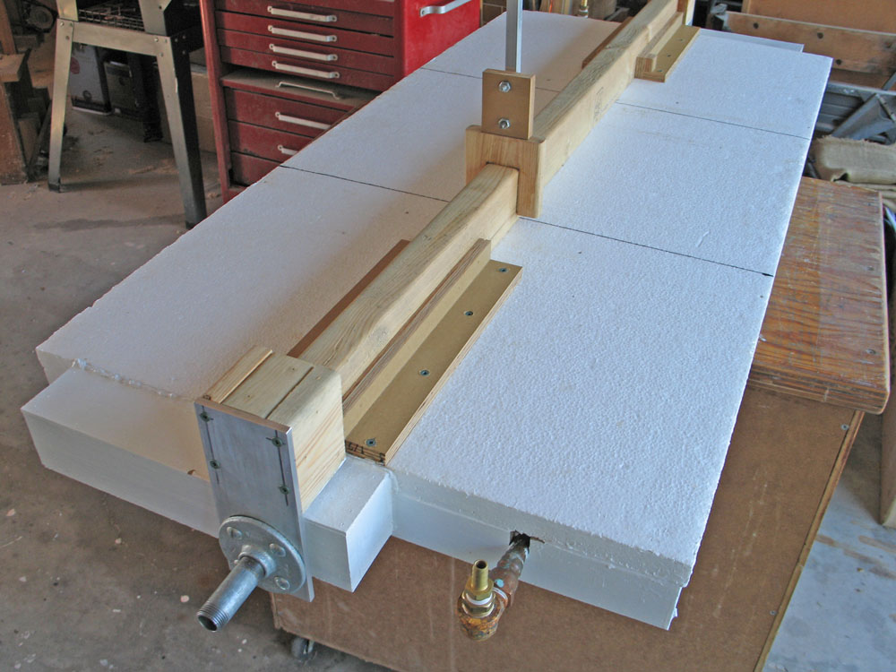
The flat plate collector that I have been using in my comparative tests was constructed as a 1/2" baltic plywood box with 1" polystyrene insulation glued on the outside of the bottom. I did it this way so that I could use staples into the plywood to hold the aluminum absorber plates in place. The construction of my flat plate collector is described here.
Shown above in a bottom view (click to enlarge), you can see also the suspension beam and one of the pivots. The linkage arm sticking up out of the top of the picture normally faces downward and it allows the collector to be rotated to face the sun. One of the fluid inlet/outlet spigots can be seen on the end.
For glazing, I used SUNTUF corrugated polycarbonate glazing made by Palram Americas. Here is a view of the sealed flat plate collector with the Suntuf in place. Suntuf is crystal clear and very tough although the sheet polycarbonate it is made from is quite thin (0.75mm or 0.030") and it seems flippy until it is fastened in place.
You can see the "wings" on both sides. I found the Suntuff hard to cut and did not bother to make the two longitudiunal cuts that I would have had to make to have it fit the collector exactly. The "wings" serve no purpose but they do not affect the function either. It was just easier that way and I was worried about cracking the sheet while cutting.
I was a bit mystified by the plastic horizontal closure strips which I bought to use with the Suntuf. The wooden versions weren't available at the store. With those, I would have simply run a bead of one of the recommended sealants along the length of the top and bottom of the closure strip but these plastic ones are all perforated so that the sealant would just drop through the holes?
I added a subframe (the solid white strip below the brown closure strip) to the top of the flat plate collector and drove cushioned screws through oversize drilled holes in the Suntuf (as they recommend to allow for thermal expansion). The sealant I used was DAP 100% Silicone Rubber Sealant recommended by Suntuf. You can see how I carefully sealed the Suntuf to the top edge of the horizaontal closure strip. I am not sure how the manufacturer intends you to use this product, their literature is silent on the sealing method with the plastic closure strips. But this will do the job.
The insulated flat plate collector is now complete and awaiting further tests.
In the previous test, the flat plate collector was fixed in position and it's performance compared to a tracking parabolic solar concentrator. In this variation, the flat plate was ganged to the tracking mechanism used for the concentrating collector so that they BOTH tracked the sun.
Flat plate thermal collectors are not normally rotated to face normal to the sun but it is commonly accepted that if tracking can be used, it will increase the effectiveness of the solar heating or PV. Since the mechanism was available (and necessary) for the concentrator, I decided to try rotating the flat plate collector.
In this view of the rear, the linkage that controls the position of the collectors can be seen. At the far end is the linear to angular motor drive that moves the assembly. The small pin with two screws parked temporarily on the beam is the stop that I used to lock the flat plate collector in a fixed position in the previous test.
At the beginning of this test I saw that the concentrator was partially shading the flat plate collector (see the first picture above). In spite of this partial shading, the flat plate started heating quickly.
As can be seen in the first picture above (best if you click it to see an enlarged view), the surface of the mirror was covered with water drops from the rain we had last night. This would tend to scatter the sun's light at the beginning of the test. I did not clean the mirror.
I also noticed at the beginning that the concentrator was not tracking true and the image of the sun was offset somewhat on the collector tube. This means lost heat as the sun's light does not completely fall on the collector. I noticed that the sensor housing had fogged somewhat and this may have contributed to the poor focus. I continued with the test. We don't get many great clear days anymore and winter is coming. I have more tests to do.
As is normal at this time of year here, the day was mostly sunny with clouds. There was almost no wind. By mid-afternoon however, the cloud cover was solid and at the end of the test, it had started to rain.
Here is the day's results with BOTH collectors tracked. As with the previous test, both collectors are UN-insulated. Tests of insulated collectors will be done next.
You will see that I added a channel for the ambient air temperature. That sensor is out of the sun under the deck, about four feet off the ground, not touching anything but air.
As noted, the flat plate starts to warm rapidly in spite of the partial shading which only lasted about 20 minutes into the test. As clouds pass overhead, the rapid cooling of the uninsulated flat plate noted in the previous test occurs here also. This is thought to be due to the large metallic surface area of the absorber plates. The concentrator is also uninsulated but it has much less metallic surface area so it does not cool as quickly.
By about noon, the concentrator reservoir temperature exceeds that of the flat plate and it remains higher for the duration of the test. The maximum is reached just before the sky completely clouds over at about 14:13 when the differential between the two reaches 17.45 F degrees (ambient is 72.4F). Even at the end of the test when light rain is occurring, the concentrator reservoir is still 16.9 F degrees higher than the flat plate with an ambient air temp of 66.9F.
I will be busy for a few days switching over to the insulated configurations for both the flat plate and the concentrator but I hope to have results from the next set of tests sometime next week.
Perhaps I should change the working fluid to 50/50 water/glycol in anticipation of winter? Brrr.
A test is described which compares a traditional flat plate solar water heater made from copper tubing and aluminum fins to a parabolic concentrating collector. Both types can be home built for significantly less than the cost of commercial units. This test compares how each design heats an identical volume of water side by side in the same sun.
You can click on any picture here to see a full size enlargement.
I built the two collectors and mounted them in a test jig (described here) which can be oriented and tilted to face the sun. The collectors are connected to identical small insulated reservoirs which contain the same volume of water. During the test, the water is pumped from the reservoir through the collector and back to the reservoir. As the test progresses, the water in the reservoir heats up. My test is modeled after the technique described by Gary Reysa at BuildItSolar. As Gary says "The collector with the better performance heats the water in its reservoir to a higher temperature, and the difference in final temperatures in the two reservoirs is an indicator of how much better one collector performed than the other."
The parabolic concentrator design (parabolic trough) is my own and is described in my plan book How to build a Tracking Parabolic Solar Collector. The sun's energy reflects from a mirror bent in the shape of a parabola and is concentrated onto a single copper collector pipe which is positioned at the focus. The water flowing in the pipe is heated by conduction with the copper.
For this test, I used a half length four foot long reflector. It is in all ways the same as the full size version except for the length. The shorter version was chosen to make the test jig more manageable. The test jig incorporates the motor drive and solar sensor as described in the book. The motor drive can control the positioning of both of the collectors in the jig although in this test, I fixed the flat plate collector stationary to match the way it is traditionally used, in a fixed position.
The flat plate collector consists of a network of copper pipe and aluminum absorber plates which are thermally coupled to the copper. As the aluminum heats up in the sun, the sun's energy is transfered by conduction to the water flowing in the copper pipe and heats the water. The flat plate collector was constructed using the excellent information at BuildItSolar.com.
I purchased the preformed aluminum plates from Tom Sullivan of U.P. Solar Solutions. The base and the sides of the box are Baltic plywood. The copper pipe was joined with conventional solder fittings. The aluminum absorber plates got a bead of silicon caulking prior to being crimped onto the copper pipe using Tom's excellent modified vise grip pliers and then stapled in place onto the base. The entire surface of the aluminum then received three coats of flat black rust paint (chromate based).
I incorporated insulation (1" polystyrene) on the back and sides of the flat plate but did not include a cover for this test. A cover will be included in a later test of "insulated collectors".
One of my goals was to make the solar size (the aperture or the effective area that "sees" the sun) of the two collectors the same so that the results could be compared directly. I didn't get that quite right:
Solar Aperture
Size (inches)
Area
sq. in.
Area
M2
Parabolic concentrator
19.25 x 48.0
924
0.596
Flat plate
20.625 x 46.0
948
0.612
So my flat plate collector has an actual effective area about 2.6% greater than my concentrator. For future tests, I may mask 24 sq. inches of the flat plate to make the two truly equivalent. For this test, I have ignored the difference. Later I also did not make corrections, the test results are as recorded.
Here is the solar test jig from the sun end. The apparatus to the right is the motor drive and the solar sensor for the parabolic concentrating collector. All the plastic pipe runs are the same length and sizes for the two collectors. The fine wires hanging from the collectors are the temperature sensors for the HOBO data recorder discussed here.
Viewed from the back, the two reservoirs (coolers) can be seen at the bottom. The reservoirs each contain 45 lbs (20.5 kg) of water and a small aquarium pump. The white control panel holds flow meters and flow adjusting valves to equalize the water flow in the two systems. The flow was measured on the flow meters to be 0.91 GPM (3.44 LPM). The pumps contribute a small amount of heat. I measured each of the pumps operating in the system and each was drawing 11 watts so the heat contribution of the pumps is small and the same for each collector.
The test was begun at 8am and discontinued about 19:30. The day began with an overcast sky but the sun broke through about 11:30 and the sky cleared until about 14:45 when unbroken clouds rolled in.
The solid line is the parabolic concentrating collector, the dashed line is the flat plate. The temperatures measured are the temperature of the water exiting each reservoir at the inlet to each collector. Throughout much of the chart, the concentrating collector temperature exceeds the flat plate by as much as 11 degrees.
The beginning of the day is interesting as the flat plate heats more than the concentrator. As the sun was not visible until about 11:30, I believe that the larger metallic surface of the flat plate was picking up heat from the air more readily than the much smaller collector tube of the concentrator. Once the tracker locked onto the rising sun, the concentrator heats quickly. In fact, both heat rapidly once the sun is visible.
Looking at the most active, mid-day portion of the chart, I have added straight lines which by eye show the heating (red) and cooling (blue) rates of several sections of the chart. It seems that the two systems heat at similar rates (the slopes of the red lines are parallel) but the flat plate cools more quickly that the concentrator (the blue lines for the flat plate slope downward more than for the concentrator. Or maybe it is just my eyes? Could it be that the larger metallic surface area of the flat plate provides better heat transfer to the air which causes it to lose heat more quickly?
This was my first test in a series that I plan to do. The weather looks overcast for most of the rest of the week. At the first opportunity, I will repeat this test, but with the flat plate ganged to the concentrator, so that they will both rotate to face the sun.
Subsequent tests are planned with insulation added to both collectors.


