Friday, September 27, 2019

battery testing 2

Using the small automatic tester to check car sized batteries takes much longer but gives useful sorting information.

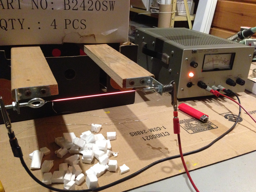
Continuing with the theme of battery testing but on a different scale, I have changed the loading of the battery tester to draw more current. The three large resistors are in series across the load terminals of the tester. The resistors are the three rectangles with my handwriting on them.

[click any pic to enlarge]

The handwriting is the measured resistance in ohms. Since the resistors are in series, the three total 15.7 ohms. Each are rated at 22 watts so the three theoretically could dissipate over 60 watts. With only 12 watts used in this test, the resistors get very hot, too hot to touch, hot enough to boil water. The metal screen helps to cool them.

I would first charge the battery fully with a separate charger and let it rest overnight. A good battery would measure in the range of 12.4 to 12.8 volts. The tester was then set to discharge the battery to 11 volts and the test started.

The tester checks the battery voltage and offers to start with a default of 10.5 volts but I did not want to discharge the batteries that low.

With a freshly charged battery the current drawn at the start of the test is about 850 milliamps (0.85 amp), or about 12 watts. This is a modest rate for a car battery. The tester is specd at a maximum current of 3 amps so this is well within its range. A load of 12 watts might simulate one charging cell phone for example or a bright LED light.

The test takes some time. I managed to check four batteries in the past couple weeks including an almost dead battery that was then returned for recycling.

I expected this battery to test weak. It had been removed from my car three years ago. It would start the car ok in the summer but was not reliable in the winter. This particular battery had continued in service here in a small solar UPS in the shop and true to form, it would last only one night in the dead of winter powering a 12 watt LED overnight. If it was cloudy the next day, the LED would not last till morning.

This battery took almost 14 hours to discharge to 11 volts and gave a result of 10.3 amp hours. I charged it again, repeated the discharge test and got 10.7. So there was some indication of repeatability to the test.

The new battery I purchased (the one in the first picture) is now installed in my car. As expected, the factory fresh battery scored well at 54.5 amp hours. It took three days to discharge!

So I now had a range for good to bad.

Continuing with three other lead acid batteries, I managed to get clear, unambiguous ratings of the battery capacities, all at the same rate.

The "old" battery that I just just removed from my car will now go to the UPS. It tested 37.2 AH.

Video is here.

Thanks for your interest.

George Plhak
Lions Head, Ontario, Canada

[update Oct 6] Great comment from Len Warner:
This is very sensible testing but one should not deep discharge automotive batteries unless there is a real need to know. However, all this seems valid: new battery tested to establish a reference; replaced car battery tested to qualify it for ups; and old ups battery tested to confirm it's ready to scrap. But the other two tests have cost you a cycle life.
Another test you haven't done is charge retention: ancient automotive batteries tend to have lost plate material, which accumulates at the bottom of each cell and shorts it out so the battery won't hold its charge long-term. It also tends to affect cells unequally, leading to cell imbalance and overcharging.
Traction batteries and leisure batteries should be more resistant to deep-cycling because of stronger plates and sumps for debris.

Tuesday, September 24, 2019

visitors

Hello!

I am humbled and grateful for your interest. And for your comments!

Each day is different. This chart is today. Usually I have more visitors from Canada.


The data is page views by country over the past 24 hours.

[click pics to enlarge]

Most often Google brings you here or you've clicked a web link. You stay to read, on average, for almost two and a half minutes!

The "bounce rate" for this site is very low, which is good. This shows that my readers stick around to read more.

Please know that I appreciate your visit!


Thank you for your interest.

George Plhak
Lions Head, Ontario, Canada

Tuesday, September 17, 2019

diy lamp update

Some learning from five years outside. I have taken down my lamps to make changes. Let's see how they are weathering.

My concept was to build simple safe cheap reliable rugged outdoor lamps using common materials: wood, found glass, cheap LED chips and "wall wart" power supplies, all re-used if possible.

It was important to me that my lamps give efficient light without drawing attention to themselves.


This one (Model upside down L) is shown attached to a corner of my deck under the railing. I mounted it low, about knee height off the ground. The light shone downward on the path and was limited upward to the horizon by the top of the lamp. There was no glare from these lamps as you walked toward them, just illumination of the path. Would the design be classed as "full cutoff"?

I am pleased with the result. They were bright! Each used only 2 watts at 9 volts from an old printer power supply. The cost was about $5 each for new and reused materials.

[click any pic to enlarge]

A gray connector box is barely visible on the other side of the post. The wire carrying low voltage DC to the lamp passes through a hole in the post to the connector box. I tried to hide the wires and plug entrances for rain and bugs. Not very well it turned out.

I liked using old glass telegraph insulators for the lamp lens although I tried all sorts of glass. Some, like the insulator, were difficult to mount, especially for outdoor year round use.

The idea was that the glass object would protect the LED chip from the elements yet pass the light in a pleasing and interesting yet effective dark sky kind of way.

A common material I used was 2x4 lumber, usually without any protective coating so that the wood weathered natural grey. I avoided cracking of the wood by selecting evenly grained sections with no knots or visible cracks. I pre-drilled all the screw holes. Cracks did form over the years but they were minor.

I had intended for the lamps to look rustic in a modern way if that is possible?

These lamps were not connected this past winter but had illuminated the pathway perfectly for the four years before that, five years total. I didn't know if they still worked.

On the bench connected to a power supply!

Perhaps I shouldn't sound surprised?

Let's have a look inside. To do that, I have to destroy them.

One of the lamps has been a bug home for a while, the other is clean, apparently a better seal.

The bug is alive. No bugs were harmed in this research!

The seal was a bead of silicone around the skirt of the insulator where it touched the aluminum sheet. I had trouble getting the silicone around where the wires went through the sheet.

The thin aluminum sheet is a piece of natural finish roof flashing. It serves as reflector, heat sink and support for the bale wire. The glass hangs from the bale wire so that the silicone has backup. The glass insulators are relatively heavy. The aluminum sheet with it's attachments form a sub-assembly that gets screwed to the wood frame enclosing the electrical part from the weather. There is a cavity in the wood to fit.

It was crudely done.

The back view before removing the bale wires and peeling the aluminum sheet away from the glass. I can see that I used both steel bale wire (the thinner rusty wire) and aluminum wire (thicker and shiny). I recall that the aluminum was easier to bend to the required shape. The steel, although thinner was more stiff.

The smaller rectangles are pieces of aluminum bar to improve heat transfer to the thin sheet. The LED chip is mounted on the other side with two screws. There is thermal compound between the chip and the bar and between the bar and the sheet.

They don't look the same because I tried a couple of variations. The one of the left was a later model. Notice that the silicone fills the holes for the bail wires but not the electrical wires!

I'll bet that's the bug entrance!

In this pic, the bug house LED is the bottom one. Surprisingly clean.

The top one has suffered some rusty corrosion to one of the two bolts but not the other.

Both LED's still work as I showed with the bench power supply. I wouldn't count on the top one lasting much longer just by appearance. There seems to be some darkening at the top corners of the COB array potting.

This LED is from the dark sky shielded lamp. As you can see, it did not do well at all. The LED no longer works.

I had used a small glass jar as a lens for this lamp. I found that it almost immediately showed signs of moisture inside the glass. None of the screws I used were rust resistant and the lid of the jar rusted badly.

The connector boxes were ok although 2 of 4 became bug houses. Corrosion of the cover screws was a problem. The screw used is an unusual fine metric thread (M4x0.5 15mm long) so finding a suitable replacement is difficult. I like these boxes otherwise for outdoor use. The one has been in direct sun and rain for five years.


This autopsy of my lamps after their "life test" shows what needs improvement. My projects are never perfect the first time!

Your comments are welcome. Please browse the other articles in the series.

Thank you for over 55,000 pageviews of this DIY Lamp series so far!


George Plhak
Lions Head, Ontario, Canada

diy landscape lamp reading list
a very bright 1 watt diy led garden light
making a lamp from a 2x4
best light at least cost - about testing bright diy leds at home
diy testing of led lamps
diy 1 watt led update
diy garden lamp progress
a shielded low power diy garden lamp
diy lamp update - this article


You might also be interested
shop lighting series

Tuesday, September 03, 2019

digital clock


Some additional detail. A short photo essay to expand on the above FB post. [the FB link does not seem to be fully live. Try this instead]

The circuit working on my bench yesterday. Link to the video. It keeps time from the 60Hz line frequency so it is pretty accurate unless the power goes off in which case it needs to be reset. It doesn't know about daylight savings time. It does not dim at night. It's big and heavy. But still pretty cool to watch.

In the very early 70s, while a student at UofToronto, I found giant neon nixie tubes at a surplus shop in the electronics market then around Yonge and Wellesley.

I was told those tubes came from the stock market display board at the TSE (now the TSX). The display tubes for this vital board were changed regularly and these were the rejects. I think they were expensive, maybe $5 each?. I was a student so couldn't afford new ones then. In the 80s, I replaced those tubes with these real NEW ones that were still available then, about $30 each. Advertised on EBay now for US$200 each for USED ones.

Digital clocks were a very hot item then and there just weren't any BIG Digital Grandfather Clocks, so I decided to build one. Because of the used tubes, this is a reuse project!

The presentation needed to be impressive so I enlisted the help of a friend who was a better woodworker. He helped me with the cabinets made from mahogany (which you could buy then) and a huge sheet of 1/4 inch smoked plexiglass. Until yesterday this clock was almost six feet tall and very heavy and awkward. It was not very stable on a floor but it never fell over! It did not have levelers at the bottom so needed shims to be vertical on a old slanted floor.

I had moved this clock wherever I went for the past 45 years. I moved it maybe ten times. It was coming apart at the bottom and needed to be fixed.

The big space under the clock was intended to house an electronic pendulum which never got built. Nor the electronic chimes. So there was really not the need for the big space. Yesterday I shortened the cabinet and made some repairs and improvements. Now it fits on a desktop or shelf.

Built with six fancy Burroughs special 17 pin sockets, hand wired and supported with a piece of wood.

The bottom of the clock board.

Mains power supply. The nixie tubes need 180 volts. The rest of the circuit used low voltage. This made both. I cannot believe it worked for 45 years!

The board layout.

Then in 1976 Heathkit introduced a digital floor clock GC-1195 and digital shelf clock GC-1197. The first commercially available digital "grandfather" clock. Popular but not a huge success.

Their display used wedge based incandescent lamps that burned out frequently. Heathkit offered a Winchester chimes option. No pendulum.


I got busy with school and never made another clock.

Thanks for your interest

George Plhak
Lions Head, Ontario, Canada


Wednesday, August 28, 2019

battery testing

Some of my lithium rechargeable cells weren't lasting as long as others.

Sorting my batteries was made easier with a simple inexpensive battery capacity tester.


I found a wide variation in my own assortment of various 18650 Li-Ion cells. Now each cell has a number, the milliampere-hours (mAh) the battery achieved on the tester.

[click any pic to enlarge]

The one pictured had been running on the tester for over an hour. At the time of the picture, that 2600mAh battery had achieved 1716mAh (the display shows amp-hours ie 1.716 Ah). The final capacity is determined automatically by the tester when the battery voltage falls below 3 volts, the test is stopped and the final Ah shows flashing on the display. For this battery, the final was 2.758 Ah (2758 mAh).

This one battery is my BEST battery and the ONLY one that achieved a result on my tester greater than what was branded. None of the rest achieved branded capacity out of 15 cells tested. Bought from various sources, my 18650's cost me between C$7 to $15 each.

The better ones are going to be used more often in my flashlights and USB power packs. The weak ones are going to help guide my purchasing decisions after they go to electronics re-cycling.

I am using the ZHIYU ZB2L3. Mine came from Banggood product ID: 1112859 in a little over a week after I ordered. The units I received were v2.3a.

ZB2L3 is a small circuit board which discharges a test battery into a resistor while measuring battery voltage and the current delivered to the resistor. ZB2L3 calculates the mAh. While testing, the display cycles three numbers and an LED at the side of the display shows alternately amp-hours, amps and volts. You can see a video here.

The micro USB cable only supplies 5 volts to the ZB2L3, not data. Since this is a complete discharge test, the ZB2L3 must have an alternate source of power hence the USB connection. Almost no energy is drawn from the USB. You can plug it into any USB charger or port. It will not charge the battery.

There is no data analysis available from the ZB2L3 other than from the display. I'd love to know that there was a way to capture a discharge curve such as this one, to explore different discharge rates and temperatures.

Two power resistors came with my ZB2L3. I used only one for all of this first round of tests. By using one of the supplied 7.5 ohm 5 watt resistors, the battery at 3.7 volts was seeing about a half amp of draw. This is (3.7X0.5=) 1.8 watts which makes the little square 5 watt resistor very hot, too hot to touch. That is why I have a cardboard sheet under the test, to protect the desktop. In hindsight it should have been a fire-proof insulating sheet. The battery gets slightly warm as it's working pretty hard.

I got the 18650 size battery holders from Banggood also. These I won't recommend. Although the battery should be held firmly against the contacts, with these battery holders it is difficult to remove the battery. The wires are very flimsy and probably contribute some voltage drop to the battery voltage measurement. Wires to the battery should as short as possible and a larger gauge wire. The contacts in this holder probably wouldn't handle soldering well. I will order better holders.

This test is a vivid demonstration of how much energy is stored in these little cells. The resistor is too hot to touch for several hours.

The ZB2L3 can be used for a range of batteries up to 12 volts and measures up to 9999 Ah. The value of the resistor can be adjusted to change the discharge rate up to 3 amps maximum but you must keep safety in mind of course.

Thanks for your interest,

George Plhak
Lions Head, Ontario, Canada

These cells, branded Ultrafire 6800 mAh show that the test gives consistent results on one type although the value is way lower than the branded capacity?!

The battery flipped over to show the branded capacity tested at only 795 mAh, the lowest of this batch of "6800 mAh" batteries.


As is my custom, this is not a paid review nor do I receive or solicit any product in return for writing. I am not selling these products. Just ideas. I don't get a commission. I don't show ads. I don't have a fundraising or patreon page.
I write in the hope that this is interesting or useful to you.
If you would like to show support for my independent work,
please consider commenting or buying one of my books? Thank you. George

Tuesday, July 02, 2019

improving cell data with a refrigerator

I have been experimenting with my cell phone as the hot spot for my home internet. The pic is my Rogers cell based internet after placing my phone in the best location which I discovered here yesterday, on a box on top of my fridge.

Rogers is offering an unlimited data plan which was a $5/mo upgrade so I took it. I intend to drop my land line based internet to save by having cell only.


My current ADSL (phone line based) internet is the least expensive plan from the only landline provider in my area, Eastlink. I enjoy slow but solid internet, 5 Mbps download, 1 Mbps upload, unlimited for $75/mo. Rogers will now cost me $80/month for their cheapest wireless unlimited plan. (see their website and the pic above)

Before yesterday, my Rogers cell data and reception were not good inside the house. And highly variable, from un-usable to outstanding. Today, reception has not changed except that I found the best location from which to access my available signal. I am pleased with what I found but there are a couple of caveats (read on).

Where I live has two negatives for cell data. My house is low in elevation relative to the two area cell towers so much of the cell signal is blocked by surrounding hills. Second, my house is covered with a metal mesh based cement that effectively shields electromagnetic radiation, like cell signals. Two negatives.

I looked at 4G cell repeaters/boosters. Hundreds of dollars and not all work with Rogers. I haven't tried one yet.

I learned about cellular booster reflectors from old satellite dishes.

Instead, I loaded an app to measure cell signal strength. I am using Network Cell Info Lite. This one is for Android.

The gauge display shows main and next best cell signal strength in dBm. The gauge updates every second or so.

Most people don't think much about where they put down their phone. Maybe you carry yours? Our phones are marvelous little radios which are sensitive to orientation and surroundings! Especially when we need them to work their best.

I have been exploring my house for my BEST signal. Signal inside my house varies over a huge range from -100dBm to -125dBm. The dBm scale is logarithmic. Lower numbers in this case are hugely better.

I can see that I am using band 12. This changes sometimes to band 4. Both of these are 800-900 Mhz. In rural areas like mine, lower frequencies like these will travel further and have adequate data rates to impress me when working well!

I don't get to pick a tower or frequency. Those are selected auto-magically between my phone and my provider.

I can see LTE on the display. This might mean 4G but it's complicated in Canada.

Yesterday I drove to the two towers that serve my area. look up your local cell towers, operators and frequencies Each is about 6 km distant, one is to the north and one is south. Using my app phone signal strength meter I measured the signal about 1 km from the towers at about -60dBm! But nobody lives there, well not many anyway...

By clicking once on a tower in the map, I learn that at the northern tower, Rogers uses 700MHz, 850 MHz and 1900MHz, Bell uses 700 and 850. At the southern tower, Rogers uses only 700 and 850. Bell is not on the southern tower. More specific information on all of the cell transceivers at a tower comes up in a table if you double click on that tower.

Back at my house, quite by accident, I found TWO spots where the signal is best. Both are on top of large grounded metal objects: my refrigerator and my clothes dryer. The metal case of both appliances is attached through their electrical cords to earth ground.

With my phone flat directly on top center of either the fridge or the dryer, my signal strength is the best inside my house. The fridge is slightly better at -97dBm.

When I check download data rate using speedtest.net from either of those spots, it is noticeably higher (twice as high!) than most anywhere else in the house!

But Upload data rate is much worse when the phone is placed directly on top of these large metal objects! It slows to less than 1 Mbps. But - if I lift the phone up about 5 inches high and place it on an empty cardboard box (about 1/4 wavelength, my phone is using 850MHz) the download data is still good and the upload data improves enormously!

Is it possible that the appliances are making a ground plane for the phone, helping with receive and transmit?

I tried different height boxes (two, three, five and eight) and the five inch seemed to be best.

I tried changing the phone's orientation, on either side, on the ends, rotating it slowly in different planes while holding it approximately 5 inches above the fridge and trying to watch the display. But placed down flat on the phone's back on the 5 inch box seemed the best (lowest) dBm reading. Minor changes if rotated slightly and slowly on the box.

I tried putting the phone over a large un-grounded metal plate on the kitchen table, with and without the 5" cardboard spacer box. The metal plate made no difference.

I rarely use my phone for voice so parking it on top of a box on the fridge is no problem for me. I can hear it ring anywhere in the house.

When I go out, the phone comes with me so the home network stops. I don't have any "smart home" devices that need always internet so this is not a problem.

If there were two phones in the house, one could set up sharing of two cell links with two hot spots (with bridging?) to further improve data rate?

If you try this, please let me know.

This experience has caused me to clean the top of the fridge. It was pretty dirty up there but cleaning had no effect on the signal strength.

Thanks for your interest.

George Plhak
Lions Head, Ontario, Canada

Update Jul 22 2019 Eastlink has been OFF since I wrote this and I have been accessing the web with Rogers cell only. I frankly haven't noticed the change, except for generally better responsiveness (plus!) and having to retrieve my cell phone off the fridge when I go out and then putting it back (negative). The actual internet data service is far superior to what I was getting with Eastlink (5mbs down 1 mps up) as this speedtest just now shows. I was worried about the throttling back "feature" but that does not seem to have happened yet. I get my latest full Rogers bill with usage and dollars on the new plan tomorrow.

Monday, June 24, 2019

hot wire foam cutter

I built a simple hot wire foam cutter to make parts for a couple of projects.

I wanted to slit a full sheet of 1.5 inch insulating foam into strips for a mooney wall. Another project, a water heater insulator, required large foam discs.

What started as quick and dirty ended up a very useful tool.


Using scrap wood, I began by adding a slot and a "fence" to a partial sheet of particleboard to make the table. The board was what I had, about 3 foot by six foot supported on two saw horses. I added a strip of wood lengthwise opposite the fence to support the front edge. The table is hung on the wall when not in use. [click any pic to enlarge]

Using particle board was problematic. When fed across the table, large pieces of foam would catch on the tiny sharp fibers sticking out of the particleboard. I later sanded and painted the top surface with several coats of latex paint which helped. It would have been better to use a smoother surfaced board.

The cutter arm is U shaped to support the cutter wire and slides in a groove under the table to adjust. It is then fixed in place for the cut.

I thought to make a variation with the hot wire slide-able to make cross cuts but haven't done that yet.

The slotted hole in the table is for the hot wire. I didn't want to cut through the fence on the back of the table. There is a minimum width that the wire can be set to, about 6 inches and a maximum of about 18 inches. The width of the slots for the mooney wall are 14.5 inches so this is a good amount of adjustment. Varying the dimensions could give other capacities.

The hot wire on the bench with power supply testing cutting action!

It turns out that the wire does not need to be red hot as shown, but just slightly less, sort of a dull red. I have an adjustable DC supply giving the wire about 4 amps at 8 volts. The voltage and current will depend on the wire type, gauge, length and the desired temperature so the adjustable lab supply is a good fit for a hot wire cutter. Normally the supply sits under the table and is connected to the two ends of the hot wire with test leads.

The wire I am using is heater wire (nichrome), typically used in toaster ovens. The first samples of wire I used were harvested from an old appliance. Later I found that I could easily buy small amounts of nichrome wire on Ebay from China so ordered 0.3, 0.4 and 0.5 mm coils.

I found that 0.4mm nichrome gave good cutting life and resistance to breaking. Getting the right temperature and the feed rate requires a bit of experimentation.

Nichrome wire expands when heated, as much as 5%, so there is a spring in the mount to put the wire under tension. When at the operating temperature, there should still be a bit of tension from the spring to get a straight cut.

The wire is simply looped through the eye bolt and wound around itself a few turns. The nuts on the eye bolts are adjusted to put the wire under tension. Normally I form, adjust and test the wire on the bench out in the open, then remove it from the arm, mount the arm on the table and then remount the wire through the slot in the table. It's easier.

Shows the smooth cut on blue type styrofoam. The edge obtained is very smooth.

Cutting foam discs with a pin through the center into the table as a pivot.

Using a thin template to guide the wire to produce a cutout in one of the discs.

Again using a template to make cutouts in one of the discs which has been already cut in half with the wire.

One of the many eight foot by 14.5 inch slabs for the mooney wall that was cut with the wire cutter.


Thanks for your interest.

George Plhak
Lions Head, Ontario, Canada

Detail under the table showing the mount for the arm made from scrap wood. The arm (with the wire removed) is inserted in a slot from the back and fixed in place with the screws that protrude to the right. Crude but adequate.

Thursday, June 20, 2019

water heater update

INDEX to the series

This graph [click to enlarge] shows the big reduction in standby energy use between my old (blue) and new (red) water heaters at different basement temperatures. The new uses much less electricity, about 25% less. Same capacity, same size heat elements. 25 year age difference.

What's changed?

The new heater has better insulation, a DIY insulated mounting base and is time of use controlled so it does not use peak priced electricity.


I will show the key physical differences between the new and old. The old was produced in 1994.

My old water heater had been quietly making hot water in the basement here for 25 years. It was not leaking and did not require replacement. It had no maintenance during the last five years with me. It worked well but could have been more efficient.

I pay tribute to this fine Canadian product by Giant Factories Inc. It owed me nothing.

To become more efficient, I purchased a competitor's product from GSW (division of A.O.Smith). Although Fergus is on the nameplate, the GSW factory in Fergus hasn't made anything in years.

I might have made a better comparison by getting a replacement Giant. Local stock product was competitive in price.

In any case, I will compare old product to new product. Both are standard electric domestic hot water heaters, now called "Automatic Storage Water Heater". Both are the same size (give or take a cm or so, I lost my actual measurements). About C$350 cost now. The technology of even the most simple commodity hot water heater has improved dramatically. Much of the improvement is federally mandated to improve efficiency. My old and new have the same capacity and the same elements but are 25 years apart in manufacture.

In other words, GSW's Fergus product of 1994 is probably much like the Giant of 1994.

So if you haven't thought about improving your trusty old hot water heater, you might save significant electricity if you do. Here is what I found:

The top of the old with the cover removed. I can see the steel tank where there is no insulation.

I am holding the anode which does not help efficiency but adds life expectancy. This anode rod (aluminum or magnesium usually about the size of my little finger) is completely corroded. An anode rod is replaceable but who ever does that?

The anode protects the inside of the steel tank by being sacrificially dissolved itself as a dissimilar metal, like a zinc anode on the hull of a sailboat. When it is gone, the tank starts to corrode so this one is well past its best before date. 25 years old! Probably never been changed.

Note the iron pipe fittings out the top for inlet, outlet and pressure relief. Copper lines were attached to these fittings with no thermal break (insulated coupling).

These UN-INSULATED metal pipes had been heat radiators into my cold basement. The pipe from the hot water outlet (the one on the left with the pressure relief valve) was always HOT to the touch. Lost heat.

Note also that the insulation inside is a glass fiber wrap with lots of empty space/air! Particularly over the very top center. Perhaps I pulled some of it off with the top? It could not have been this bad could it?

I didn't determine how the steel tank was supported inside the steel can but there must be some metal support structure from the tank to the outside which would probably cause some heat loss.

The new heater has about 2.5in / 6-7cm of foamed in place insulation at the top near the center. I am measuring to the steel tank through the anode access.

In fact I had to dig out some insulation to get access. I wanted to look at the installed anode. The top of the anode rod bolt will be my measuring point for water tank temperature once I insert a sensor and cover/insulate the opening I have made in the insulation.

The anode access has a cute cover plug but once removed, you need to dig out the foam down to the hex head on the anode bolt.

Note the insulated fittings for hot and cold on the top of the tank. The pipes that lead to these fittings are no longer warm to the touch.

Likely the foamed in place insulation completely supports the tank mechanically (unlike glass fiber) so no need for a bridge structure hence lower heat loss.

The fitting to the drain valve at the bottom of the tank was an iron pipe to a metal valve. Both good conductors of heat to the basement.

The old tank used to sit right on the cold concrete basement floor.

"Verified for Energy Performance" in 1994!

The drain is now a recessed plastic valve, a much better insulator.

I've raised the tank off the floor on an insulated base, making it easier to do the annual residue draining and reducing the heat lost to the cold concrete floor.

The wooden base (about 8 inches high) is topped with a 1.5 inch foam disk.

The diameter of the base is larger than the water heater by about the thickness of a batt of rock wool insulation. It could have been a square platform to be simpler to make.

I will wrap the entire new water heater with an insulating blanket after installing seismic straps. Not required by the code here but a good idea anyway for a 100 year event. Earthquakes do occur in Canada.

Time of use inhibit I wrote about here.

I plan to install direct energy metering for the water heater as it is one of my top energy consumers. NRCan on water heaters. Note that there are no storage tank electric water heaters that are Energy Star rated. I think mine will qualify when finished!


Thank you for your interest,

George Plhak
Lions Head, Ontario, Canada.

INDEX to the series

Nameplate for the old Giant.

The date code means the tenth month of 1994.

Nameplate for the new GSW lists Fergus, ON CANADA for address of manufacture?