Showing posts with label lighting. Show all posts

Thursday, March 12, 2020

fixing led string lights 2

Addendum to fixing led string lights.

An example of fuses in a string. Two of the tiny 10mm 3A fuses down in a recess in the plug.

[click any pics to enlarge]

I found it helpful to use a small flat screw driver to push open the tiny cover.

Tiny fast blow 3.0 amp 10mm fuses. You can buy them at Amazon in a larger lot for about 50 cents each. Beautiful laser engraved printing on one end cap.

I've had a chance to look carefully at two strings of more recent (2018 manufacture) from the same company. One has 25 C9 bulbs (top) while the other has 35 C6 bulbs (bottom).

There are significant changes in the strings to what I described previously.

I am sorry to say that the LEDs on both newer strings are NOT REPLACEABLE. I highlighted the corrosion that appeared in the ones I looked at earlier. Apparently the manufacturer has done away with "repair-ability".

Fuses protect from overloads if the user, for example, plugs too many strings together in series. Only the C9 string has fuses in the plug, the C6 string does not. The C9 string came with two spare fuses in a small baggy taped to the plug. Two fuses protect both the line and the neutral since the plug and socket are not polarized.

If either of the two fuses is blown (open circuit) the LED string will not light, nor will another string plugged into it at either the end socket or the feed through socket on the back of the plug. Both are fed by the fuses.

The bulb assemblies of both are masterpieces of precision injection molding. These will not come apart without damage. Probably water tight except for the plug and socket.

The same 3 wire arrangement is used on both newer strings. Two conductors go from plug to socket to carry the line circuit to the next string. The LEDs in the string are all in the third line, down the center if you will. At the plug end, the LEDs connect to the fuse side of the line. At the socket end, the LED string connects to the neutral. Actually, the plug and socket are not polarized, so there is no line and neutral in that sense, but there really is!

There is no canister containing extra parts like resistors or blocking diodes in the newer strings.

Except for the two LEDs nearest the ends, all LEDs have two wires out the bottom. All are in a series string. There is no physical indication of polarity (cathode/anode) on the outside of the bulb assembly, so if you are going to be cutting them out of the string, you'd better mark for orientation or be prepared to test for polarity later.

The end LEDs have three wires coming out the bottom. On each, two of the wires are connected together and to one side of the LED. The third wire is to the rest of the string. The C9 bulb string is pictured.

It is worth noting that at each end, it is the center conductor of the 3 wire LED base that goes to the socket or plug.

Thanks for your interest

George Plhak
Lions Head Ontario Canada

This is an addendum to fixing led string lights.

Tuesday, September 17, 2019

diy lamp update

Some learning from five years outside. I have taken down my lamps to make changes. Let's see how they are weathering.

My concept was to build simple safe cheap reliable rugged outdoor lamps using common materials: wood, found glass, cheap LED chips and "wall wart" power supplies, all re-used if possible.

It was important to me that my lamps give efficient light without drawing attention to themselves.


This one (Model upside down L) is shown attached to a corner of my deck under the railing. I mounted it low, about knee height off the ground. The light shone downward on the path and was limited upward to the horizon by the top of the lamp. There was no glare from these lamps as you walked toward them, just illumination of the path. Would the design be classed as "full cutoff"?

I am pleased with the result. They were bright! Each used only 2 watts at 9 volts from an old printer power supply. The cost was about $5 each for new and reused materials.

[click any pic to enlarge]

A gray connector box is barely visible on the other side of the post. The wire carrying low voltage DC to the lamp passes through a hole in the post to the connector box. I tried to hide the wires and plug entrances for rain and bugs. Not very well it turned out.

I liked using old glass telegraph insulators for the lamp lens although I tried all sorts of glass. Some, like the insulator, were difficult to mount, especially for outdoor year round use.

The idea was that the glass object would protect the LED chip from the elements yet pass the light in a pleasing and interesting yet effective dark sky kind of way.

A common material I used was 2x4 lumber, usually without any protective coating so that the wood weathered natural grey. I avoided cracking of the wood by selecting evenly grained sections with no knots or visible cracks. I pre-drilled all the screw holes. Cracks did form over the years but they were minor.

I had intended for the lamps to look rustic in a modern way if that is possible?

These lamps were not connected this past winter but had illuminated the pathway perfectly for the four years before that, five years total. I didn't know if they still worked.

On the bench connected to a power supply!

Perhaps I shouldn't sound surprised?

Let's have a look inside. To do that, I have to destroy them.

One of the lamps has been a bug home for a while, the other is clean, apparently a better seal.

The bug is alive. No bugs were harmed in this research!

The seal was a bead of silicone around the skirt of the insulator where it touched the aluminum sheet. I had trouble getting the silicone around where the wires went through the sheet.

The thin aluminum sheet is a piece of natural finish roof flashing. It serves as reflector, heat sink and support for the bale wire. The glass hangs from the bale wire so that the silicone has backup. The glass insulators are relatively heavy. The aluminum sheet with it's attachments form a sub-assembly that gets screwed to the wood frame enclosing the electrical part from the weather. There is a cavity in the wood to fit.

It was crudely done.

The back view before removing the bale wires and peeling the aluminum sheet away from the glass. I can see that I used both steel bale wire (the thinner rusty wire) and aluminum wire (thicker and shiny). I recall that the aluminum was easier to bend to the required shape. The steel, although thinner was more stiff.

The smaller rectangles are pieces of aluminum bar to improve heat transfer to the thin sheet. The LED chip is mounted on the other side with two screws. There is thermal compound between the chip and the bar and between the bar and the sheet.

They don't look the same because I tried a couple of variations. The one of the left was a later model. Notice that the silicone fills the holes for the bail wires but not the electrical wires!

I'll bet that's the bug entrance!

In this pic, the bug house LED is the bottom one. Surprisingly clean.

The top one has suffered some rusty corrosion to one of the two bolts but not the other.

Both LED's still work as I showed with the bench power supply. I wouldn't count on the top one lasting much longer just by appearance. There seems to be some darkening at the top corners of the COB array potting.

This LED is from the dark sky shielded lamp. As you can see, it did not do well at all. The LED no longer works.

I had used a small glass jar as a lens for this lamp. I found that it almost immediately showed signs of moisture inside the glass. None of the screws I used were rust resistant and the lid of the jar rusted badly.

The connector boxes were ok although 2 of 4 became bug houses. Corrosion of the cover screws was a problem. The screw used is an unusual fine metric thread (M4x0.5 15mm long) so finding a suitable replacement is difficult. I like these boxes otherwise for outdoor use. The one has been in direct sun and rain for five years.


This autopsy of my lamps after their "life test" shows what needs improvement. My projects are never perfect the first time!

Your comments are welcome. Please browse the other articles in the series.

Thank you for over 55,000 pageviews of this DIY Lamp series so far!


George Plhak
Lions Head, Ontario, Canada

diy landscape lamp reading list
a very bright 1 watt diy led garden light
making a lamp from a 2x4
best light at least cost - about testing bright diy leds at home
diy testing of led lamps
diy 1 watt led update
diy garden lamp progress
a shielded low power diy garden lamp
diy lamp update - this article


You might also be interested
shop lighting series

Monday, April 15, 2019

series parallel

I wondered about the recent web traffic here from MIT (Massachusetts Institute of Technology).

I visited the referring link and found some of my work at MIT Circuits and Electronics Spring 2019 Lab 9 (scroll down to "The Challenge"), illustrated with one of my diagrams and a concept from my piece on fixing LED string lights.

I am honored. Welcome MIT students.

The MIT labs are pretty cool. There is recommended music! For Lab 9 "Tesla - Modern Day Cowboy"

I had illustrated a concept with actual data as a waveform on a 40 year old Tektronix storage oscilloscope, something that today's students will probably never see. Likely why the MIT author turned that into a graph. The MIT function generator has menus, mine has knobs.

But the physics remains the same.

Thanks for your interest!

George Plhak
Lions Head, Ontario, Canada

Thursday, April 11, 2019

updated bench lighting

Showing off my updated NASA level bench lighting installed this week along with a general cleanup.

[click any pic to enlarge]

A four foot single tube 18watt LED costing C$15 runs the whole of the shelf above the bench at about eye level. It shines down and back. The lamp is attached to the shelf at each end with two bendable strips. The beam of light has a smooth broad focus. I can change where it points without getting the main light in my eyes.

My primitive light meter shows 106-108 foot-candles in the center of the desk. Quite bright. Good enough for NASA soldering. I don't do soldering for NASA but if it is good enough for them, I'm happy.

Most of my projects are shoe box size so there is plenty of space on the bench. The "device under test", parts, tools, wires, paper and other stuff tend to litter the bench once underway but nothing on the bench has to be there so it cleans up nicely between projects.

The lighting is unobtrusive yet right at eye level. Light floods the entire volume of the bench top. There are no shadows.

AC sockets on both sides make it easy to plug in additional stuff as needed. A variable AC supply (Variac) and meter tucked in the back corner make it easy to control test AC power.

A very bright space for only 18 watts and $15. I haven't seen it done quite this way. Lights under shelves on the other hand go back to at least the 60s?

The shelf above the bench holds test equipment that is actually more visible with slightly subdued light so having the task light under the shelf is a benefit to the arrangement.

I used plastic cable clamps to hold the wire and switch. Light control is via WiFi or RF remote but the product's hard wired switch is my backup control.

My office got the same treatment. The shelves are conveniently 4 feet long. The lamps were mounted in the same manner, hung from the shelves with flexible straps cut from pipe strapping.

Previously, I could see each of the monitors well but I could not easily read paper on the desk in front of me. My head and shoulders would cast a shadow of the overhead room light onto the desk ahead of me to make reading difficult. Now the desk surface is all uniformly and comfortably lit.

Experimenting with the position of the monitors relative to the lamps by sliding forward or back on the desk. Seems to work best when the monitors are more or less under the lamps. Fine adjustment is easy.

I have the lamps in the office plugged into one Sonoff Basic RF switch which I can control in the usual way with eWeLink or a Sonoff key fob switch.

Thanks for your interest.

George Plhak
Lions Head, Ontario, Canada

The LED maker claims 1850 Lumens but I can't measure Lumens.

Lumens (light) can be complicated...(a flashlight testing example)


shop lighting reading list
a parabolic workshop light
led household bulbs
exploring efficient workshop lighting alternatives
work light led retrofit
testing fluorescent light fixtures - the test jig
testing fluorescent light fixtures - the test method (video)
testing fluorescent fixtures - 40 watt
efficient workshop lighting 2
updated bench lighting (this article)


You might also be interested
DIY lamp series

Monday, August 27, 2018

efficient workshop lighting 2

Lighting a work area in a pleasant, safe and efficient manner is about more than just changing light bulbs. I have changed some bulbs, added a few, tried new LED plug in florescent replacements and cleaned the rest. Big improvements! Low cost once you have modern electronic ballasts. Re-use the existing steel box which is often superior to what you'd buy new.

This is a view of my fabrication shop with ALL the lights on. [click any pic to enlarge] The lights in this room are almost NEVER All On. One of my principles of efficient lighting is to only use what I need. I have five lighting "zones" in this one room so I can have the amount and location of lighting that I need.

I switch my lights manually and I am pretty good at remembering to turn off when I leave the room. I tried motion sensing switches but they annoy me. None of these lights are network controllable, all are manual!

When I arrived here five years ago, there were four dual 40 watt T12 florescent lights on the ceiling switchable in two banks. The lights were along the sides of the room. The lamp fixtures were old and some of the lamps didn't work. Some of the fixtures had already been reused and were painted deep red.

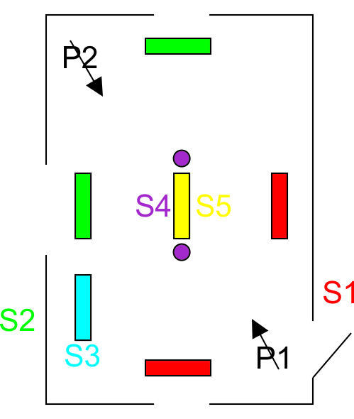
Switching on the lights caused interference on my FM radio. See exploring efficient workshop lighting alternatives The title picture is approximately the same view as this article, five years ago (called P2 on the plan below).

Those four fixtures are in the same places (the green and the red banks) but they are now completely rebuilt with new electronic ballasts, new T8 32watt lamps and new lamp mounting posts.

Originally, there was no light in the center of the room. I added a circuit to the panel for an "island" in the center of the workshop ceiling with switchable lights (purple and yellow on the diagram) and a hanging power pendant. Both the lights are controlled with pull switches. Yellow is a High Output (HO) dual 50 watt T5 florescent (100 watt total) and purple are two LED bulbs, each 10watts (20 watt total).

The two LED bulbs provide the lowest level of illumination in the room at a cost of only 20 watts. Perfectly adequate basic illumination from two points near the center of the room.

Later, I added another pull chain controlled dual four foot 32watt T8 fixture over another bench in the bottom corner (blue). This is the fixture I used for the test below.

At move-in the ceiling was dirty white. I painted the ceiling with two coats of pure white latex in patches as I removed fixtures for rebuilding. Now, after four years, the ceiling is again turning a dirty white but not as bad as it was. I should probably repaint it.

Taking down and cleaning the now four year old T8 bulbs has made a huge difference in the room brightness.

The lamp showing the lettering was facing down, the other one is showing the "up" side, the side you normally don't see, the side facing the fixture. The accumulated dirt/dust cuts down the amount of light leaving half of the lamp.

Cleaning! So simple yet so effective! A lot of climbing the ladder in the last two days as I inspected and cleaned the eight fixtures that are now on the ceiling.

I also tried two new LED "instant replacements".

From Philips "InstantFit T8 LED, C$12 each at Home Depot. I bought one each of "daylight" (6000K) and cool white (5000K) so I could compare them. I had intended to buy two of the 6000K and that is what I will end up with since I have decided to return the 5000K after trying it out. The Philips 6000K seems subjectively brighter to me in my shop environment.

I bought Philips 32W replacement LED lamps a couple years ago and have been using them in the paint area. I have been pleased with them, judging them to be similar brightness to 32W fluorescent lamps but instantly full bright but twice the price. I believe two years ago, the Philips LED lamps were on sale at C$30.

I notice that now, the Philips lamps are glass. The earlier ones were encased in a plastic tube which would bend just slightly. The new Philips tubes also have lots of warning labels including about fire hazard. Perhaps the glass is needed for high temperatures? The lamps certainly do get warm, almost as warm as florescent.

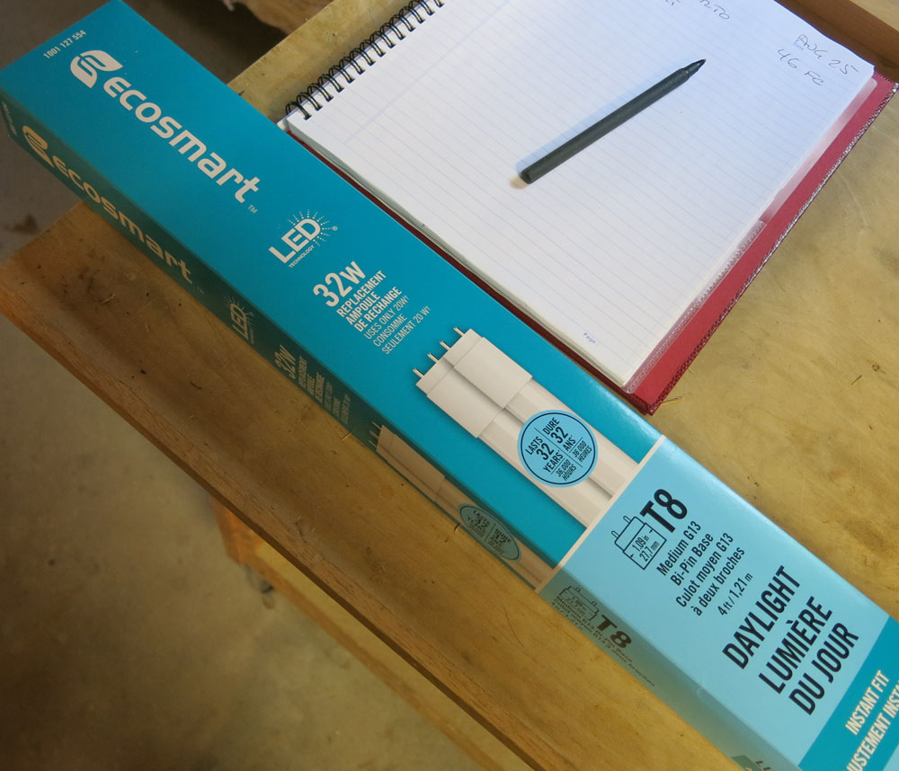
The second type I tested was from Ecosmart, their 32W LED replacement (rated 20w each lamp), two in a pack for C$15 also at HD. Also glass. Far less warning info. Very bright!

Curiously, Ecosmart calls their bulbs "daylight" at 5000K. The naming of color temperature is a bit of a wild west I think, the degrees Kelvin should be a better guide or actually comparing in your own environment. Some time ago I did a piece on comparing conventional, compact florescent and LED bulbs and compared some of the visual effect of different color temperatures.

I installed the Philips and the Ecosmart bulbs in several different fixtures here but made measurements at bench height from the blue fixture


Comparison of lamp types
LampBrightness FCTemp (5 min)
Philips ALTO 32w florescent4635C
Ecosmart 20w LED5233C
Philips 17w LED36.526C

The Philips are not as bright as my typical T8 florescent. The Ecosmart is the brightest. The Ecosmart uses less power than the florescent, but more than the Philips LED.

Temperature was measured with an infrared temperature meter. Brightness was measured with a footcandle meter.

One detail of the comparison is that the LEDs came to full brightness immediately whereas the florescent takes several minutes to come to full brightness. Even longer at near zero temperatures. So the LED has a real advantage in my shop in winter.

Another detail is that general ceiling lighting is good for benchtop brighness but several of the machines, even with light fixtures directly over them, regardless of lamp type, need work lights ahead of the blade since the machine itself shields some of the overhead light. The band saw and the radial arm saw are examples that will need more attention for better safety.

Thank you for your interest,

George Plhak
Lions Head, Ontario, Canada

shop lighting reading list
a parabolic workshop light
led household bulbs
exploring efficient workshop lighting alternatives
work light led retrofit
testing fluorescent light fixtures - the test jig
testing fluorescent light fixtures - the test method (video)
testing fluorescent fixtures - 40 watt
efficient workshop lighting 2 (this article)
updated bench lighting

Sunday, February 22, 2015

testing fluorescent fixtures - 40 watt

My first test in a series is this old florescent fixture with magnetic ballast and big T12 40 watt tubes which had been on my shop ceiling for years. It used 90 watts to give 60 footcandles illumination in my test jig at room temperature of 15C. The power factor was excellent. The ballast caused no FM interference. In spite of the leakage of potting compound, it had given an excellent 25 years of service.

Although this wasn't the first test that I did, I thought I would present it first since this is representative of old magnetic ballast and T12 fluorescent tube technology. I had four fixtures like this one on the main shop ceiling.

click any pic to enlarge

This is the condition of the test ballast, an old Canadian General Electric "Gold Label" 17A240E. It works but you can see that the potting compound has been leaking. At room temperature, the black potting material is hard. In fact, it was somewhat difficult to remove the fixture cover since the potting had effectively glued it shut.

I found a reference to this ballast which says that GE sold their ballast division to Alliance in the late 80s. On the back of my GE ballast, I found the code "9002" which might translate to Feb 1990. Elsewhere on the fixture, I found "4 90" which might mean April 1990. My readers will know my fondness for mature technology which stands the test of time. Although this fixture shows it's age, I am impressed that it seems to have given almost 25 years of good service!

The lamp holder posts in this fixture were dirty but in fair condition. There is no broken plastic and the contact fingers did not seem to be distorted or burnt. If I refurbish this fixture, I will likely clean these posts or replace them with new ones. I used them for this test.

It is worthwhile to examine these posts carefully if they are going to be reused since people who try to remove and replace tubes can easily damage these posts if they do not understand the correct way to do this.

The bulbs I used were from the fixture. They are older Sylvania 40 watt T12 Cool White tubes that show some blacking at the ends opposite the lables, shown in the bottom half of the picture.

I did three runs with this ballast at three different temperatures. This involved a run early in the morning when the shop was cold (room ambient temp about 1C). Then another later in the morning about an hour after the wood stove was lit (average temp abut 6C). Finally a third run mid afternoon when the stove had been running for several hours at an average room temperature of about 15C.

The graph shows that the light output (in footcandles) increases as the lamps run over the first ten minutes and then levels out at some steady value. As the temperature of the ambient air increases, the lamp output increases also.

I was pleasantly surprised that the lamps even lit at 1C since in my experience, some cold morning days in the shop, some of the lamps would not light up, or would not light up for some minutes.

The label on the GE claimed a power factor of 90%+. My measurements showed that the power factor was indeed greater than .90 within 5 minutes of startup. At room temperature of 15C, the power factor reached 0.97 after ten minutes. At the lowest temperature, power factor reached 0.93.

The label on the GE ballast claimed line current of 0.8A and this was certainly close except in the start up situation (less than 5 minutes operating) when it used slightly more, up to one amp.

The instantaneous power use was remarkably constant at the different tempertures and times, varying between 84 to 88 watts, as measured on the Kill A Watt meter.

My actual raw test data is available here as test10.pdf.

A troubling result of these tests was that the temperature of the old GE kept rising, up to 51.6C by the end of an hour from an ambient starting temperature of 13C. It was so hot in fact that more of the black potting compound had started to ooze out of the ballast by the end of the test and it was quite gooey in viscosity. Clearly there is something not quite right about this ballast and it will have to be scrapped. I wonder what it might be like after several hours operating in the summer, when the ambient temperature is more like 30C?!

Some older ballasts contained PCBs. I found this GE document which states that ballasts manufactured after January 1979 do not contain PCBs so this one does not. Further, it describes the potting compound as a mixture of asphalt and sand so the black ooze is no more hazardous than pavement.

One good thing about this old GE ballast is that it did not create any FM radio interference - none. This was even without having the fixture grounded which I found gave better interference results with some of the newer electronic ballasts.

In summary, this old technology magnetic ballast and T12 40 watt tubes, admittedly not new tubes, used about 90 watts to give 60 footcandles illumination in my test jig at room temperature of 15C. The power factor was excellent. The old ballast caused no FM interference. In spite of the leakage of potting compound, it had given an excellent 25 years of service. I did not attempt to measure anything about the color of the light produced.

The condition of this magnetic ballast should make us think carefully about products which claim to "retrofit" older magnetic and T12 lighting with newer versions by means of an adapter like this one. Better to assess the condition of what you have in case you discover ballasts like this one that really should be replaced?

I have a series of tests to post in the coming days comparing different fixtures as alternatives to this one. This old fixture will be the reference against which the others will be compared.

For background, this interesting article "The Fluorescent Lamp" with many pictures traces the history and workings of fluorescent lighting, from the Edison Tech Center.

Thank you for your interest.
George Plhak
Lion's Head, Ontario, Canada

shop lighting reading list
a parabolic workshop light
led household bulbs
exploring efficient workshop lighting alternatives
work light led retrofit
testing fluorescent light fixtures - the test jig
testing fluorescent light fixtures - the test method (video)
testing fluorescent fixtures - 40 watt (this article)
efficient workshop lighting 2
updated bench lighting

Friday, February 13, 2015

testing fluorescent light fixtures - the test jig

Continuation of work done last year, described in this article.

Here at georgesworkshop.ca I have eight dual four foot ceiling mounted fluorescent fixtures. I want to add more light in the center of the main shop, probably two more fixtures, so ten altogether. The purpose of this work is to compare a variety of alternatives to come up with safe, modern high efficiency shop lighting while re-using as much as possible from the existing fixtures.

TEST JIG

(click any picture to enlarge)

Because I wanted to do a series of comparisons, and it is not very convenient with the fixtures mounted on the ceiling, I built a simple test jig from wood scraps to temporarily hold a fixture to be tested at a standard height above a table (about 38").

The feet of the jig also can support a fixture off the table when I want to remove the cover to attach a thermocouple to the ballast or other changes. Some of these fixtures have sharp edges and protruding screws out of the backside that might scratch or damage the table surface. The two shelf brackets support the fixture when it is in the raised position yet allow easy changeover between fixtures and access to the bulbs.

A light meter will be positioned on the table surface directly below the center of the fixture.

INSTRUMENTS

I used a number of instruments to measure the energy into the lamps and the light output. None of these tools are particularly special or expensive. Since I would be making a series of comparisons, the absolute accuracy was not as important as consistent results and I would achieve those results by making careful measurements in the same way (as much as possible) between the various alternatives.

The light meter I use is a generic, made in China, bought on Ebay. Mine measures in footcandles and I used it on the most sensitive scale (200 footcandles full scale). I have just looked at "light meters" on Ebay and meters of this style and class sell for about CAD$25-50. Mine gives stable and consistent results and for my purposes, to know whether one source is relatively bighter than another, the absolute accuracy is not that important.

One footcandle is equal to one lumen per square foot or approximately 10.764 lux.

To help get consistent results, 1) I started the tests with a fresh 9 volt battery, 2) I placed a masking tape cross-hair on the table top so I put the meter head in the same place each time if I had to move it and 3) I tested the light meter before each fixture under an LED table lamp nearby (not shown) in the same position under the same bulb and ensured that I got the same reading each time before beginning the test run.

To measure factors about the power input to the fixture, I am using a "Kill A Watt" meter from P3. I have an older version that I have used for a number of years. The current model of what I have is a P4400 but mine seems to be the same.

The Kill A Watt plugs into a power outlet (in this case a Woods extension cord) and itself has a socket on the front into which I plug the cord to the fixture I am testing. The Kill A Watt makes its measurements on the electricity which passes through it to the load, the fixture I want to test.

I use the Kill A Watt to read the voltage, the current (in Amps), the Power (in watts) and the apparent power (in VA). The built in timer is also handy for telling how long the test lamp has been ON. I make a series of measurements at 5, 10, 15, 20, 25 and 60 minutes and after each measurement, I set the Kill A Watt to show elapsed time to help prompt me for the next measurement.

To measure temperature, I use a two input Fluke model 52II. Since there is a significant change in gas tube (fluorescent) light output with the temperature of the gas, it is useful to know the room ambient temperature. When the fixture first comes on, light output is less than when the gas warms up. The gas warms due to the electricity passing through it. At low temperatures, such as early morning in the shop during winter, the older fluorescent fixtures may not light at all.

The Fluke 52II uses two thermocouples to sense temperature. One of the thermocouples is shown in the picture, the small bead at the end of the wire. One thermocouple was loosely attached to a wood beam across the top of the test jig about the same height as the fixture, but not touching it, just hanging in the air. The other sensor I used to measure the temperature of the ballast in the fixture.

I included the auto transformer so that I could vary the voltage. I didn't do this during the regular test runs but experimented separately with varying the voltage on only some of the fixtures to see how sensitive they were to reduced voltage. It turned out that they were not very sensitive (well regulated).

The Woods extension cord which the Kill A Watt is plugged into is itself plugged into the auto transformer. The auto transformer is plugged into a regular grounded wall outlet in the shop.

In case I have confused you, here is a block diagram.

I have one more objective that I have not fully figured out yet. I want some measure of the color temperature or spectra of the lamps. By now we are probably all familiar with the desirability of "warm white" light as opposed to "cool white". Without an expensive spectrophotometer, such as one of these, I must improvise.

I think that by laying a sheet of white paper under the fixture, where the light meter normally sits and taking a photo in RAW mode with my excellent Canon G15 camera that I should be able to make some judgements or measurements of the color temperature with Photoshop or some other program that can read the RAW image. In RAW mode, the file produced by the camera is an uncompressed, unaltered record of the data produced at each pixel without any compression or compensation (like white balance).

If you have any ideas about how to do this, please leave me a comment below (I moderate the comments to prevent spam so they appear after I approve them) or write to me directly at george at ffwdm dot com.

This is the test jig in operation. I have tested a number of fixtures already with different types of gas and LED tubes and a variety of ballasts. I am recording and graphing the data and will present the results in upcoming posts.

Thanks for your interest!

George Plhak
Lions Head, Ontario, Canada


shop lighting reading list
a parabolic workshop light
led household bulbs
exploring efficient workshop lighting alternatives
work light led retrofit
testing fluorescent light fixtures - the test jig (this article)
testing fluorescent light fixtures - the test method (video)
testing fluorescent fixtures - 40 watt
efficient workshop lighting 2
updated bench lighting

Thursday, January 02, 2014

work light led retrofit

My portable work light until recently used a 500 watt quartz halogen bulb. That was dangerous because it got hot enough to burn.

Now it is an LED light which uses only 10 watts and barely gets warm while throwing lots of light.


I have retrofitted the light to use two $2 each 10 watt warm white LEDs. The LEDs run at half their maximum power from a reclaimed printer power supply which now hangs underneath the light. The LEDs get DC from AC via the power supply. Not as bright as with the halogen bulb but plenty bright enough for most situations where it will be needed.

Because of the low power consumption and the low heat produced, I think it is much, much safer than before.

The cost of parts for my conversion was about $6 ($3 for the two LEDs on Ebay from China and about $3 for a used HP printer power supply at the local recycling center, also a bit of aluminum sheet and bar and a few tie wraps and screws, possibly another dollar?). It took a pleasant evening to sort out the method and to do the conversion.

Unfortunately, I did not take a "before" picture. The light that you start with might be different from mine but I think these were very popular five, ten years ago? This is a general guide. Some of my other relevant work with LEDs has links.

The first step in my retrofit was to remove the halogen lamp and its supports and contacts as well as all the high voltage (117VAC) mains wiring from the housing. The parabolic reflector and a mounting bracket were the only parts saved.

This is the halogen lamp and its porcelain supports and contacts, now discarded. (click on any picture to enlarge it)

This pic shows the two LEDs mounted on the reflector. Note that the existing reflector was used as a part of the heatsink.

Another view of the reflector showing the sandwich of two aluminum bars and aluminum sheet with the reflector. The small screws hold the sandwich together and hold the LEDs firmly to the heatsink.

This is how it goes together. The technique is similar to what I am doing with the diy garden lamp. The 1 inch aluminum bars acts as a heat spreader from the LEDs to the aluminum sheet and the existing reflector which provide a large surface area.

I laid out the holes on one bar, drilled them carefully and then used a punch to transfer the hole positions to the other bar. I drilled the second bar and the center hole in both and then used a medium sized bolt through the center hole to clamp everything together to drill the small holes through the existing reflector and the aluminum sheet.

Not shown in the diagram is the heat sink thermal compound which is applied in a thin layer between the parts as they go together. In this closeup, you can see the thermal compound at the top edge of the aluminum bar as well as the mounting and the wiring of the LEDs.

I am using a reclaimed HP printer power supply rated at 18 volts DC at 2 amps. I wire the LEDs in series so that each receives about half the total, or about 9 volts. At this voltage, the LEDs will conduct about 350mA so the power supply has much more capacity than is required. The power supply stays cool.

This is the spreadsheet with the test results I got for the particular LEDs that I am using. The LED tests are described here

This picture is taken auto no flash with my Canon G15. There is no other lighting except for the LED work light. I have found that it is challenging to show you lighting results, but I think that this picture is pretty accurate.

Thank you for your interest in my work.

Please see my other lighting projects at the tab above.

George Plhak


shop lighting reading list
a parabolic workshop light
led household bulbs
exploring efficient workshop lighting alternatives
work light led retrofit (this article)
testing fluorescent light fixtures - the test jig
testing fluorescent light fixtures - the test method (video)
testing fluorescent fixtures - 40 watt
efficient workshop lighting 2
updated bench lighting