Wednesday, November 28, 2012

fixing led string lights

LED lamp strings can be repaired. It can be as simple as replacing one failed bulb but can be more complex. Often it is not easy.

Early preventative maintenance, a dab of grease into each socket when new will help prevent corrosion caused failures. These strings could last much longer if the manufacturers did this for us at minimal cost. But you can do it yourself. Keep these strings running and out of the landfill.

**NEW** Mar 12 2020 Please see the Addendum for some updates and new pictures.

Don't LED lights last forever?

Apparently not, particularly when used outside.

Winter is very damp here in Canada. Water gets into everything, including supposedly sealed outdoor lighting. The water causes the LED leads to corrode and fail. This corrosion failure of LEDs due to water can be completely and easily stopped with a dab of grease, if caught early.

Failed bulbs that you can see should be replaced promptly since they cause the rest of the string to be under more stress and may lead to more failures. I had the kind of failed bulb that prevented the whole string from lighting. Both kinds of failure can occur.

Like most of us, I bought into the LED low power and eco friendly thing a couple of years ago. I threw out the old filament bulb outdoor Christmas lights and bought new GE branded outdoor LED string lights.

Yesterday, while getting ready to put up the Christmas lights, I found that two out of eight strings did not work. Each has 25 LEDs. I spent part of the day exploring why those had failed and putting up the rest. Fortunately I had tried them before putting them up!

(click any pic to enlarge it)

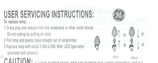
My GE strings are supposed to be repairable. They come with instructions (the full copy, a pdf) and spare LEDs.

The worst part about my two failed strings was that none of the bulbs lit up. Not one or two bulbs that weren't on while the rest worked. The failed bulb could not be seen since it kept all the others from lighting. This meant that each bulb had to be pulled and a working bulb inserted (according to the manufacturer's instructions).

I thought that we had abandoned series wired light strings back in the 60s? Series wiring is back with LED lights!

I can remember my dad back in the day proudly showing off a new parallel wired string, with which one failed bulb would not darken the whole string. He had spent many a time finding a failed bulb in a dead string so he knew the advantage of parallel wiring. From then until now, the advent of LED lighting, most of our filament bulb lighting strings were wired in parallel.

Series wiring is back with LED lights! It turns out that there is a technical reason why LEDs need to be wired in series and this will be discussed below. Since they are wired in series, I need to check every LED bulb if none of the string lights. Any one of the LEDs could be open circuit.

There are 25 LEDs in each string so that is 25 decorative caps to pull off and then 25 LEDs to pull out. Some of the caps come off easily, others do not. I found that a drop of WD40 helped free some of the stubborn caps. I dripped the lubricant onto the joint between the cap and the socket.

Some of the caps broke when I pulled them off, usually a part of the sealing ring was left in the socket. I dug out the debris from the socket and discarded those caps and replaced them with spares from the scrap strings. The caps are keyed and only fit on one way. Why they did this I am not sure.

I admired the first class molded parts that made up the socket assembly including the LED holder, the cap and the base. There was no flash and the parts fit together very exactly and securely with a snap. With ideal plastic that did not weather or change dimensions or properties with UV and temperature, these would be really nice parts. After a couple years outside, some are harder to get apart than others.

Pulling out the LEDs was sometimes problematic. I used my fingernails inserted in a small groove between the LED and socket and just pulled. Here also, a bit of lubrication from the dielectric grease helped with subsequent removals.

Throughout all this pulling on the socket, I tried not to pull on the wires. They seem securely crimped into the terminals but I thought it best not to pull too hard on them. The terminals are a potential point of failure so while the LED was out of the socket I took a look at the joint with the wires and the condition of the terminals before dabbing the grease and re-inserting the bulb. The inner (insert) portion of the socket can be removed and that will be described below. I found it was desirable to remove the insert on those where corrosion was seen in the socket.

It's about RUST

The cause of my failures was common corrosion. Each LED is itself encased in clear plastic but the metal leads that form it's connection with the socket are made of iron or steel and these leads rust if exposed to water and oxygen. The socket weatherproofing can be improved with a dab of dielectric grease to prevent the oxygen and water from reaching the point where two dissimilar metals touch: the LED lead (iron) and the socket contact (some other metal). Why wouldn't the manufacturer do that?

If I doubted that the LED leads were ferrous, here is a picture of the rusted ones stuck to a small magnet. You can see a broken off LED lead in the foreground.

I have opened all the bulbs on three of my LED strings so far. One that I scrapped had a high percentage of failed bulbs 8 out of the 25. Another that I did not scrap had only one of these problem bulbs. All of these bulbs failed because the LED leads rusted. Some of the LED leads had fallen off or rusted completely through.

Probably millions of these string lights will end up in the landfill over the next few years because people will give up on them. Hopefully you can use some of these ideas to help you to locate the problems with your own and keep them going for a few more years.

Understanding how LED string lights work

You do not have to cut the LED string apart and unwind it as I did here but it helped my understanding of how the thing was put together and I am going to use this picture to explain what I found.

Parallel wired light strings have two wires down the length of the string and each lamp is wired between the pair of wires. These LED strings have three wires down the length. It is a little difficult to see what is going on unless you do what I did with a string that was damaged beyond repair. I separated the string into two parts by clipping at only one point. I could then unwind the string into it's two sections as revealed in the picture above.

This is a schematic of my LED string. I clipped the wire at the bottom of the canister. The center portion, the string of LEDs, can then be separated from what I've called the extension cord portion. You can see in the schematic, the wires across the very top and bottom connect the plug at one end to the socket at the other. The series string of LEDs is inter-wound, but is separate from, the extension cord except at the very ends where the LED string and the canister join the circuit, across the two hot leads.

So you can see the LEDs are all in a string and that if any of the LEDs fails open, the current flow in the string will be interrupted and the entire string will be dark. Unlike filament bulbs which rarely fail shorted LEDs can fail in this way. No light is produced yet current continues to flow through the LED. It is thus easy to see which LED failed since it will be the dark one.

It is interesting that in the GE instructions, they seem to presume that the LEDs will fail short and you should look for dark ones and replace them. This was not my experience. All of my failures were failed open circuit, due to rust.

I sacrificed two of the canisters to dissection for the cause of this project. You can see that my method improved after I learned to cut through the cover sheath at the joints of the inner cylinder. There are two 2000 ohm 1 watt resistors and a diode wired in series on a three section frame. Kind of a clever thing. No signs of water ingress with either one, unlike with about 10-20% of the lamp sockets. But I had to look to see what was in here.

I'd like to point out the excellent writing of Terry Ritter "LED Christmas Lights and How to Fix Them". Terry has been down this road and he writes about how LED strings work and what he learned with strings made by Philips. These I have from GE seem very similar.

Terry describes that the LEDs are arranged in series strings because they do not tolerate high voltage well. The voltage that comes from a wall plug (120VAC in North America) is high voltage to an LED which normally operates from a few volts - 3.1 volts in the case of my white LEDs. By stacking 25 of them in a string, each LED drops 3.1 volts so the total voltage drop across the LED string is 77.5 volts. The resistors in the canister are used to drop the remainder (120 - 77.5 = 42.5 volts).

Interestingly, if LEDs fail short, they increase the voltage drop on all the other components in the series circuit so the resistors get hotter and all the other LEDs pass more current. So you can see why GE tells us to "replace failed bulbs promptly" because the whole string goes into overdrive mode if LEDs fail shorted. If they fail open, the whole string goes dark and no current flows.

Terry found that the Philips LED string contains a small fuse in the plug end. If the fuse blew, the string would not light. Do I have a fuse? No mention of a fuse in the GE pamphlet. I attempted to find such a fuse and went so far as to destroy the stacking plug end of one of my rejected strings. I think I can say with authority that there is no fuse in the GE unit. Maybe where Terry is, they need to have a fuse? You should eliminate that possibility, that you have a fuse. Sometimes the "fuse" is thermal and permanently cuts the circuit. Something like that would be in the canister, with the resistors.

Terry talks about failed LEDs being dark and easy to spot, so obviously he saw lots of the failed short type. Not here. Terry wrote in 2007 so perhaps the LEDs are different now. He uses LEDs of different colors whereas mine are all white.

Terry also mulls the lack of a blocking diode in the Philips string and suggests that manufacturers add a blocking diode to better protect the LEDs from reverse transient voltages and it seems that GE listened to his advice and added such a reverse blocking diode in the canister.

Finally, Terry points out that running LEDs from AC means that the LEDs are only on for a part of the time leading to a flicking effect.

I attached a current meter to one of the wires in the GE LED string and displayed the results on an oscilloscope to show what Terry is describing.

The green oscilloscope trace shows that most of the time (the flat part of the trace), the LED is OFF and for about 1/3 of the time, 60 times a second, the LED string conducts hard, up to about 44 mA maximum and then goes off again. 44mA is a lot of current for an LED of this size which would normally run at between 10-20 mA current if it was continuous or DC current. I suspect that the string would appear much brighter yet use the same cost of electricity if the string was operated from DC rather than AC.

I will look at that possibility in a future article.

Fixing the LED sockets

The main failure mechanism I had to deal with was rust in the sockets (rust is an insulator) and deteriorated LED leads.

The LEDs with deteriorated leads (any sign of rust at all) were discarded and replaced. Fortunately GE had supplied a number of spare bulbs (about six) with each string. Working ones from the scrapped strings provided more spare bulbs and caps.

The sockets were cleaned in the following way. I found that it was possible to separate the sockets into two parts by pushing out the inner section with a small blunt tool. You can lay the socket with its open face flat on a surface and push hard on the center, between the wires, to free it up. Then if you pick the socket up and push, the center portion should just come right out.

This picture is a bit ugly with the socket guts covered with Vaseline, the dielectric grease I had handy. This socket was particularly badly coated with rust and the LED leads had completely disintegrated so it is the one I wanted to show you.

It is interesting that in any galvanic pair of metals, it is one metal that corrodes and the other is fine (more about galvanic corrosion). In the case of these sockets, the LED lead suffers but the contacts are ok except that they are coated with rust. With the socket disassembled it is very easy to get at the top edge of the connector to clean it up. This one has been together for a while potted in Vaseline which seems to be lifting the rust residue which is fine, both the Vaseline and the rust are insulators. The point of the Vaseline is to keep water and oxygen away from the LED lead and the place it touches the conductor in the socket. You can see the bright metal edge on the socket conductor where I have scrubbed it with a small screwdriver to clean up the edge. It is only these top edges that touch the LED leads, you don't need to worry about cleaning up anything else. To re-seat the contacts, just push them back into the socket. They will click into place. The Vaseline helps to seal the joint where the wires enter the socket also.

Finally, I ran a bead of Vaseline around the base of the cap before inserting it into the socket. This improves the lubrication so the cap is hopefully easier to remove next time and the film of Vaseline would help to seal the joint between the cap and the socket, helping to keep out the water.

Hopefully these lights will continue to give good service for years to come.

Your comments are welcome. Thanks for your interest and good luck with your LED light strings.


George Plhak
Lion's Head, Ontario, Canada

**NEW** Mar 12 2020 Please see the Addendum for some updates and new pictures.

Apr 2019 - I wondered about the recent web traffic here from MIT (Massachusetts Institute of Technology). Welcome MIT students!

You might also be interested in my series on
a very bright 1 watt diy led garden light

Wednesday, October 24, 2012

diy anemometer

I was organizing here the other day (a rare thing) and I came across this DIY anemometer (do it yourself wind speed and direction indicator recorder) that I had built in 2002 according to Derek Weston's excellent DIY Rotorvane design. What a nice thing Derek helped me build!

I should be putting it outside but I will do that at the new place. For now it has to be put away. Should run it over the winter to make sure it still works OK? It does not really go anywhere until the spring. Hopefully this winter will be mild but there will be storms and it is a bit of a thrill to see how strong the wind got the night before, for example. I have a great tall post to mount it on which is mostly in the clear. It is in the house's shadow but the wind almost never blows from that direction (usually from the NW here).

This was a very nice DIY project for me with wonderful instructions, software and personal help from Derek via email. His webpage isn't live any more but Chris' site has a very thorough review of Derek's device.

I have just installed the RS232/USB driver and now Derek's software and manual which I'd saved on a CD with the device. It turns out that was a good idea since neither is available on the web. If you need either, let me know by email.

As I write this, I am having trouble getting the anemometer to talk to the computer thru COM1 via the RS232/USB adapter. When I spin the cups, the LEDs on the display track the movement so I can see it is responding correctly but I can't read it from the computer. It only "speaks" RS232 so I need to remember how to do that. I dropped the speed to 1200bps but that does not get it going. Update 10/27: I have it working now with a straight through RS232 cable. Not sure why the RS232/USB adapter does not like it.

By itself, the anemometer will store a months worth of readings and it can be remotely located. Here is a sample of the log in printed form that I was able to produce with Derek's software.

Ten years ago I had assembled the display easily and it worked well. There was a fair bit of fine soldering but no surface mount components which suited me just fine. Many LEDs mount in the board at the same height. It worked on the first try.

Derek's rotor assembly is particularly clever, robust and precise, all at the same time.

I was a bit skeptical of my ability to make the cups out of ping-pong balls as Derek described but I got very respectable results by simply being careful with a very sharp blade. I did a couple trial runs to get a bit of practice. The ping-pong balls were inexpensive and available anywhere thus illustrating an important principle of DIY projects - that the materials should be readily available anywhere and cheap to obtain.

Derek had a great small kit of the circuit board and some of the special parts like the machined spindle and the disk but I am assuming that is no longer available. Derek had explained on his website when you could see it that he had sold the rights to the design to a business and that there were a limited number of the kits available.

Derek, if you are sailing out there somewhere and want to say hello, please write to me! This was a great project - thank you. Nicely done.

George

Monday, October 01, 2012

reader project

Bruce from Florida about his solar concentrating hot tub heater which he built after reading my book:

Hi George,

Thanks for the compliment. I stand on the shoulders of giants (like YOU). {blush}

It has worked out very nicely. It actually produces WAY TOO MUCH heat in the spring and summer. It goes past 108°F and trips the hot tub's overheat safety circuit. (I'm adding a thermal sensor that plugs into the Arduino) As you can see I have it in series with a passive unit my friend built. I may bypass that in the summer and use just the array. Now that I have it working, I'm of course working to refine it, simplify and miniaturize it even more.

I'm planning on building a Tiki hut near the hot tub and putting the array on the roof of the hut facing south. That would give it at least 2 more hours of exposure per day. It will also give me my back yard view back. Right now the whole contraption dominates 1/2 of my little back yard. But what a conversation piece.

I will make the Arduino kit available eventually. I still have some tweaks to do. Right now I'm fine-tuning the routine that dynamically switches in and out of "timed mode" when it gets cloudy on a sunny day.

You probably noticed some things about the operation of the tracker movement. It never goes backwards to search the sun. That was a concept I decided to tackle when I read one comment on the internet "You can count on the sun to never move backwards". I thought that was funny and true… most of the solar trackers actually hunt for the sun moving west AND east. You are surely right— that little amount of movement east doesn't matter much energy-wise, but it still irritated me. It wasn't "elegant".

The other thing you may have noticed is the speed. My array moves way faster than others. That's thanks to the combination of the speed of the processor and the sensitivity of the garden light's PV "sensor" and the fact that I'm only moving 4 little 4-foot troughs. I'm sure the little screwdriver could not move your big array without being geared down. It takes less than 30 seconds to return east. Seeking the sun happens in less than 1 second. There's no wasted energy and a minimum of irritating motor noise and wear on the motor.

The drive setup is cheaper and more compact than yours, that was one of my goals there. The one thing I don't have that yours has is spring isolation from the motor to the array, but so far it hasn't been necessary. I think the advantage of its positioning under the array, not extending out the side makes up for that flaw.

I also the idea of putting the 'brains' in a fishbowl in the heat of the sun worried me. Here in Florida, I could imagine a china-syndrome happening. That's what steered me towards putting the controller down below, with just the "eye" up on top. Plus, I was itching to do something cool with the Arduino. What a fun and powerful development platform that is!

I will be able to eventually have the whole control system manufactured at a fraction of the size and cost. Everything is based on easily available and inexpensive components.

$20 for the screwdriver, $14 for the shower door wheels, I got a shop to cut and thread a piece of Delrin with standard 13 threads/inch for $25. The "housing" for the motor is a 2" conduit body $8. The Arduino, sensors and relays altogether cost less than $40.

I tried using my own voice on the video, but I alas, am the world's most sleep-inducing narrator. I ended up using one of the speech voices on my Macintosh and I think it adds just the right touch. I slowed it down quite bit to sound more like the real me. Also I worked on the video to add interest and humor. Version 1 without those elements was un-watchable.

-Bruce

You can write to Bruce via Youtube.

Some more pics and description of Bruce's project

Projects from Andrew Gray (US) and Sulaiman (Jordan) shown in videos.

reader projects
reader project 0
reader project 1 this article
reader project 2
reader project 3
reader project 4
reader project 5
reader project 6

Thursday, September 27, 2012

diy testing of led lamps

I had done some testing of LED lamps available to me to rank them for brightness and efficiency. I went through several interations of a DIY test method to help me select a lamp for my 1 watt DIY garden lamp project. Here is a part of the assortment that I tested back in February. I have a few more I'd like to try so this is ongoing.

I wouldn't normally do this for just one lamp, but the idea is to create a prototype for something that could be reproduced on a limited "craft" scale as a DIY project. Perhaps a dozen or so to surround a garden or guide a walkway? Or even a hundred?

My goal of making the maximum attractive light from only 1 watt of power is arbitrary. 1 Watt is an impressively sounding small number but it could be any amount. As it turns out, 1 watt can produce a very impressive amount of light. I will describe a simple but effective test method that helped me to rank LED's.

You can modify this any way that makes sense to you. It does not become dangerous until you start looking at the line voltage 110/220 operated bulbs. I don't think you need to involve line voltage in powering an outdoor system except where it plugs in to keep it safe - so all of the LEDs I tested were of the "12 volt DC", automotive or flashlight type.

I had gathered LEDs from various sources and I wanted to be able to compare them in some semi-organized fashion. I wanted to be able to measure the amount of light produced and the power used by each one. I wanted to observe the light they produced in as objective a manner as possible, but simply.

click any pic to enlarge

There is a bit of basic electronics and physics involved but it is pretty easy stuff. The equipment you can usually borrow or get used what you need at low cost. You don't need it very long, just for the tests. This is a schematic of my LED test setup. The variable power supply allowed me to vary the electrical input to the LED in a smooth manner. I don't say whether it is AC or DC since either could be used. I'll talk more about that later.

Two of the meters allow me to measure the VOLTAGE and CURRENT flowing in the circuit loop, through the LED and back to the supply. From the voltage and current, I can calculate the POWER (the watts) used by the LED. With a ideal variable supply, I can vary either the voltage or the current or both.

The lightmeter lets me measure the light produced. There are different types of light meters and I will talk a bit about that. I was lucky to have a very nice old instrument from Tektronix called the J16 that allowed me to measure either foot-lamberts or mW/sq.cm.

This is the actual test setup. I took this picture in the daytime but daylight through the window affected the tests, particularly when I used the ft-lambert sensor so all of my later testing was done in the dark. The cardboard box is around the J16 lightmeter and the variable supply and the meters are to the right.

You will see that the LED I am testing is mounted on a little frame above the J16 and both of them "look" the same way, towards a bright white sheet of paper taped to the wall in front of them, inside the cardboard light box. In the first pic above, you will see a number of LEDs mounted in these frames. I made them out of scrap wood, all the same size (about 15x8cm)so that they would clip onto the J16 easily and could be swapped around. I tried to mount the LEDs (which were all shapes and sizes) so that the main emitting surface was about level with the surface of the frame and mounted at its center.

In this way, I tried to have a similar environment for all of the LEDs. The LED and light meter are about 55cm from the white paper which is tabloid or north america B size paper. It is what I had available. You can use whatever size of sheet and setup that makes sense for you, but the idea is to keep it the same for all of the LEDs as much as possible.

Thank you for your interest.

George Plhak

diy landscape lamp reading list
a very bright 1 watt diy led garden light
making a lamp from a 2x4
best light at least cost - about testing bright diy leds at home
diy testing of led lamps - this article
diy 1 watt led update
diy garden lamp progress
a shielded low power diy garden lamp
diy lamp update

Related: Fixing LED Strings (Christmas Lights)

Thursday, September 06, 2012

diy solar reflector squeegee from a car wiper

I get questions about cleaning my parabolic solar concentrators.

Concentrating collectors might have a mystique about them that because they use mirrors, these mirrors have to be perfectly clean. This is not possible in the real world and not really necessary I have found. As with a flat plate type collector, the reduction of output due to atmospheric grime might be in the order of 10% if the equipment is really dirty.

Adding a transparent cover over a parabolic collector does not solve the problem since the grime accumulates on the cover instead. Adding a cover means that some energy is always lost by the cover, even if it is clean, since the cover will absorb some of the heat and re-radiate it so that heat does not make it to the collector.

Here in my northern climate (Toronto Canada area) rain water cleans my solar concentrator reasonably well. My array is at an angle to the ground and most of the grime just slides away with the rain runoff. I have not cleaned them myself until now.

To maintain peak efficiency ALL types of solar collectors benefit from manual cleaning, even if only once a year, a concentrator is no different. Some atmospheric deposited grime does not wash off with the rainwater and a mild mechanical cleaning is required. If you are in a dry climate, you might need to manually clean your solar collectors more often.

If the concentrator mirror is on the backside of the sheet as it is with a plastic mirror, a squeegee is perfect.

This is about my DIY tool for cleaning concentrating parabolic solar collectors similar to my DIY design very easily. Like using a regular straight squeegee on a flat plate collector.

Recently I noticed the shape formed by the windshield wiper on my car when I pulled it away from the glass. It was almost perfect - a backwards parabola of almost the right size. But the rubber blade was on the wrong side!

click any pic to enlarge

I disassembled a standard auto wiper to invert the blade and mounted it on a pole. As you will see in the video below, it is now almost a perfect fit with my parabolic collectors.

Above is a closeup to show the swivel pin which holds the wiper to the curved arm. I looked at four types of car wiper blades to check for curvature and length. A friend came up with this rather ingenious method of fastening the blade to the arm. thank you Peter! Simple yet very tough, it allows the blade just the right degree of support and a small amount of give. Details will be in the upcoming book.

If you want to make one of these cleaners, you will need to look at the type of wiper blades you have available.

I tried OEM blades (my drive is a Ford product) and universal replacement blades I bought from an auto supply. I found that by removing the end caps (twisting and pulling) each blade could be easily disassembled. With all but one of them, the blade could be reversed.

If you are in Canada, the one I finished with and show in these pictures is the "Horizon" by rain-x available in various lengths from Canadian Tire.

I ignored the packet of rain-x that they suggest I apply to the glass prior to wiping. I didn't think it was necessary. I used a 22 inch blade for my 24 inch collectors. I am surprised that this product is sold here in inch lengths with no metric marking at all on the package? Canada is metric I think

Getting the center pivot onto the other side proved the most challenging. Of the four types of wipers I looked at, they all had removable end caps but all differed in their details. All but one could be reversed. One had too much curvature. One was too short. It was difficult to remove the center pivot and involved gently bending metal fingers and breaking a spot weld but I did it.

This cleaner works very well. The reflector must be wet before using it. You can do it after a rainfall or use the morning dew. Otherwise you will need to mist with a water spray to the point that water droplets start running down the surface.

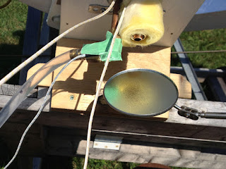
This is the parabolic squeegee in action. The pole it is attached to is the common expandable type sold in the home centers for applying paint. The arm is bent in an arc to miss the collector tube. Only light pressure is needed to keep it in contact with almost the entire reflector surface. You can make another two passes to catch the very edges of the reflector sheet if you want to do that.
I don't see many people on their roofs cleaning their collectors - maybe that's a business idea for someone?

DIY concentrating solar reflector squeegee from a car wiper from George Plhak on Vimeo.

Thank you for your interest
George Plhak

[to the gen2 intro and reading list]

Saturday, September 01, 2012

new uses for old tv towers 2

Old television tower sections are low- or no- cost structural components that can be re-used for horizontal spans like this small footbridge that was made over a single weekend. The boards I used for the top and sides are salvaged 2x4's that otherwise would have been scrap.

(click any pic to enlarge it)

Many of the towers around here were made by the Delhi Metal Products company (now Wade Antenna), manufactured in Delhi, Ontario. Typical towers are bolted together of sections that are each 10 feet (300cm) in length. The top section is different and has the antenna mount platform. The sections are made of 18 ga. steel tubing with welded rungs. If they are in good condition, they are very strong, even if used sideways.

The galvanized zinc coating has probably mostly dissolved away in it's mission to protect the steel. Many of these old towers are standing un-used as we've switched, most of us, away from off-the-air TV.

I wanted a small footbridge across what we call here the "seasonal stream". The amount of water varies but at wettest is more than we can jump. It seemed a perfect place for a small bridge. Two or three of us can stand on it and it does not sag at all. Not unpleasant to look at and certainly functional.

The sections I used for this bridge had been sitting by the family cottage for years since being taken down. There were two of the regular sections and a top section. I took the top section to the metal scrap dump and took the other two home.

In a tall tower, you may have more sections. These towers with guy wires sometimes reached four or five sections. If still standing, towers are extremely dangerous to take down and if they are to be re-used, some care is required so that there is no damage. The bolts are rusty and the task is not fun if you have vertigo. There are people who do this sort of work and you probably should hire someone with insurance to do it.

Tower guys are also a good source of supply. For another project, a sun deck, I needed four tower sections and those came from a tower guy. He even let me pick very nice ones from his stock yard that matched.

With tower sections at hand my first step was to clean them with coarse steel wool and wet sand paper and examine them carefully, rung by rung to see if there was any damage. I wanted them strong. In my case, I had to have a couple rungs re-welded to the tubes as they had been broken loose.

I then moved the towers to the bridge site and primed, painted and let them dry in the sun while I thought about the foundations.

The foundations were simple. The tower legs rest on a patio "stone" of precast concrete, the pair cost about $10 and were the first of only three things I had to buy for the project. The rest of the material was recycled.

I did have some loose gravel and bedded the stones on about six inches. I also placed some loose real stones against the stream side to slow the erosion a bit. Three years later, that has held up fairly well. I will probably rework the foundations a bit. Maintenance is easy. With two people, one at each end, the bridge can simply be lifted off its foundations and moved aside.

Here is a view from underneath to help me explain the mounting system for the planks. With the Delhi towers with the round tubes, I used plastic clamps of the kind used to hold down plastic conduit. The planks don't actually get screwed to the tower but are captured by the clamps. This seemed easier than trying to drill into or through the tower tubes. I measured the diameter and then went looking for clamps to fit. I splurged on stainless steel screws to hold the clamps to the planks. The clamps and screws where another $15. I thought that the plastic clamps would be good underneath where they aren't so exposed to sunlight so even if they are not listed as UV safe, they should be fine. The plastic won't rust.

I realized at about this point that I would have to watch for rungs as I spaced out the planks since they might interfere with the clamps. So I did a mock up and laid the planks and slid them around. The clamps could go towards one edge of a plank if necessary yet still keep the plank tied to the tower. When I had an arrangement that seemed to work, I fastened the two end planks at both ends of the bridge with their clamps and worked inward toward the center.

I used a string attached to the two end planks and stretched it to form a guideline. You can see how that helped me in this view. Without the string, it would have been uneven at the edges.

I cut all planks in the shop on a crosscut saw set with a length stop. Working from a pile of salvaged 2x4s, I selected sections that were sturdy and cut them out of the scrap, all to the same length. Some had been painted, some not. Some pressure treated, some not. The best of the pile. The balance now was firewood. The pressure treated cuttings went to the landfill (I always keep PT separate), but so much less. Most of the scrap was used in the bridge.

The finishing touch is a strip of wood down each side fastened to each plank with a stainless steel screw. These tie the planks together so they don't move when you walk on them and also help define the edge. I had tried it before these were added and it just didn't seem as safe.

These strips are cut from the scrap 2x4s like the planks except in this case, the scrap wood is sawn lengthwise.

Probably I should add a kick board at the end and a yellow hazard strip? So the fox and coyotes can see it. They do use it. I see their trails over it in the snow.

This small footbridge has been weathering nicely here for three years. The most of the old paint has fallen off the recycled planks and the bridge is starting to look uniformly gray. It feels sturdy and safe to walk on. The old tower sections look like they will useful for at least the next 20 or 30 years or so.

Thanks for your interest!

To the first new uses for old TV towers

You may like another bridge project.

Sunday, August 26, 2012

how to make solar superheated steam

Demonstration and measurements on superheated steam produced with a self made linear parabolic concentrator using a mirror and an evacuated tube solar collector. Easily tracked concentration of about 1:15.

Steam from the sun on a small DIY home made scale could be used to clean drinking water or to make electricity. I don't think that I have seen it done quite this way.

Before now, my solar concentrator efforts have related to heating a home swimming pool. Making steam was something that happened by accident, usually when we forgot to turn on the circulation pump. Making steam was generally not a good idea around a swimming pool. Besides, that system was designed for high volume, low temperature rise and it does that job well. Making steam on purpose requires some changes.

Yesterday I made steam with the sun intentionally on purpose. My test is crude but it shows what is possible with determination, a few tools and a hardware store.

I set up this test specifically to make steam and to measure the amount produced using the Gen2.0 design DIY solar concentrator. This is only a starting point, a first test.

Last year, I had shown with a similar setup that temperatures of over 600°F (>316°C) could be reached in the evacuated tube at the focus of my home made parabolic trough. I was a bit concerned that there might be trouble with the glass when the relatively low temperature of boiling water was initially introduced. Would it crack and implode the evacuated tube?

(click any pic to enlarge)

In a way, this was an unremarkable test. Once I learned how to start the process and to set the operating point of my equipment, the steam production was steady and reliable.

Because it was a bright sunny day, the steam at the outlet was almost invisible. I don't have the obligatory astonishing pic/vid of large plumes of steam to show you, but it was there. Most times, the only way I could see the steam was to place a dry mirror at the outlet. The mirror would be instantly covered with beads of condensed water from the steam that I couldn't see. Steam production was steady and it was extremely HOT. I measured temperature of 472.2°F (245°C)!

disclaimer

I tried again two days later and the steam is NOT VISIBLE. I measured over 500F. If it has not occurred to you that this is DANGEROUS, you should not read any further - seriously - I take no responsibility. Please be careful if you think you are going to try this at home.

Steam that is hotter than the boiling point of water is dry steam or superheated steam. There is no liquid water in the steam. This is good. If you want to have absolutely clean water or you are running a turbine to make electricity, you want dry steam.

Because this is a focused collector, it needs to face the sun. I had attached my home made reflector motor drive and tracking but I didn't use it. During the one hour test duration, I simply nudged the reflector position about every 15 minutes or so. Position and therefore focus did not seem to be very critical but that deserves more attention. This was a pretty rough test.

By the end of one hour I turned about 1-1/2 cups of water (actual was .334 KG) into steam. That works out to a heat input to the water of 208 watt-hours or 750KJ. I don't address efficiency in this test.

Equipment Description

Here is my test setup for the steam test. I am using a four foot (122cm) version of the Gen2.0 parabolic reflector with a six foot (180cm) glass evacuated tube suspended at the 10 cm focal line. The reflector can pivot around the evacuated tube on ball bearing mounts. The test stand has been used in previous tests and is described here.

On top of the ladder is an open top reservoir of water, actually the windshield fluid tank from a 1990 Honda Accord. I had intended to use the small pump on the tank to inject water into the collector but ended up not doing that but simply relying on gravity and the vertical position of the tank to inject water up to a desired level in one arm of the collector (the boiler or "up" leg). Moving the tank to different steps on the ladder accomplished that quite nicely.

I am re-using the rather burnt-out looking collector assembly that I last used for the stagnation test. Although it had over-heated previously since it had no cooling (a definition of stagnation), the solder joints did not fail and it does not leak so I decided to put it to one more good use for this test.

At the yellow arrow, you can see that I have attached a thermocouple (the silver object) to the copper collector by over winding tightly a short length of copper wire. This thermocouple I have called T4 and its purpose is to show the temperature of the steam just before it exits to the air. The fitting to the bottom left will be the outlet, the fitting to the top left will be the inlet. The yellow bung of fiberglass wool is shown wound between and over the collector pipes and the thermocouple wires. When the collector is inserted into the evacuated tube, the bung seals the opening in the tube creating a solar "oven" inside the evacuated tube. The water and the steam will not touch the inside surface of the glass but remain inside the copper tubing. The copper mesh provides some heat coupling between the collector and the inside of the evacuated tube. The mesh may not be necessary.

More details on the construction of this collector.

This schematic view shows my test setup. At the left is the open top water reservoir coupled to the inlet of the collector through a short length of poly tube. The collector forms an inverted U inside the evacuated tube. The outlet of the collector is simply vented to the air as you can see in the first picture above. Also in that pic, you can see the location of the inlet temperature monitor T2 under the green masking tape which holds T2 to the inlet coupling. The purpose of T2 is to show the temperature of the water going into the collector.

The schematic shows the collector as vertical but in fact, the collector, the evacuated tube and the reflector are tilted approximately 45 degrees on the test stand to make them normal to the direction of the sun at my latitude. I did not attempt to get the orientation EXACTLY right. As I said, this was a rough test. I used the shadow of the reflector counterweight to show that the orientation was more or less correct.

T1, the ambient temperature thermocouple is located in the shade under the small table.

T3, the "boiler" temperature thermocouple is located on the collector "up" leg, attached in the same way as T4, approximately co-incident with the top of the reflector or about at the top of the concentrated beam from the reflector. It was intended to show the temperature of that portion of the collector, in the steam above the boiling water.

In a perfect world, I would have the reflector length match the length of the evacuated tube but I have these fine 180cm evacuated tubes to work with as well as 122cm reflectors so the evacuated tube sticks out of the top of the reflector beam for about 20% of its length. A refinement to make for a future test would be to have the reflector better match the evacuated tube and collector. Evacuated tubes are commonly available in standard sizes as I discussed in "more about evacuated tubes".

I believe that it is desirable for a home DIY project to have a type of "flash boiler" in which the water that enters is almost immediately flashed into steam. This would mean very little stored energy in the boiler (safer operation) and a short thermal time constant, meaning that the system would start to operate quickly as there was not a lot of water in the boiler to heat to the boiling point before steam could start to be produced.

Ideally, water would be injected into the inlet at a constant rate to match the rate at which steam is produced. I had planned to do this by regulating the speed of the reservoir pump by changing the supply voltage. Then I realized that a simpler approach was also possible with some compromise to the "flash boiler" concept and that is the approach described above with setting the reservoir on different steps of the ladder to achieve different fluid levels in the boiler.

Operation

As I said above, I had intended to use the small reservoir pump to feed the collector "boiler" but I was concerned about introducing water into an already hot collector and also about matching the rate of evaporation with the feed rate of the pump. My attempts to feed water in short bursts or at a slow rate simply lead to angry bursts of steam from the outlet and then nothing as the collector cooled down and evaporation essentially stopped until the collector (and the water it contained) heated up again.

The compromise was to try different vertical levels of the reservoir and to not use the pump. Lifting or lowering the reservoir causes the fluid level to correspondingly rise or fall in the collector, like with a fluid manometer. As water boils and evaporates, replacement fresh water will flow in and the level will stay the same as the level in the reservoir.

With the reservoir at the top of the ladder, the water level was too high and the steam that resulted came in bursts with burbles of liquid water, often in violent bursts. You can see the water on the table in this enlargement. The puddle was actually quite a bit larger earlier in the test. I interpret this as liquid water being kicked over the top of the U and then exiting the outlet with the steam. Liquid water is not good in the output of a steam generator. Operation was not steady.

With the reservoir a couple rungs down the ladder, the steam flow was steady but seemed to be coming at a lesser rate. So by trying a few variations, I found the second step from the top of the ladder, or a water level in the collector about 1/2 way up the boiler section of the "up" leg gave steady steam with no burbling, in other words, no water at all coming out at the outlet, just steam.

To start, I set the reflector out of focus. The evacuated tube was fully exposed to the sun but not concentrated sunlight. This allowed the interior of the tube to heat without solar concentration as it would normally do in the water heating application where these tubes are typically used, without a reflector. I left it this way for about one hour to preheat.

It is interesting that in this condition, without the reflector, no detectable steam was produced. In other words, the collector did not get hot enough to boil. In my previous stagnation test, the collector was empty and the the collector temperature soared. By keeping the boiler about 1/2 full of water it is heated close to the boiling point but did not reach that (without concentration). T3 - the temperature at the top of the boiler, was about 250°F (121°C) and T4 - the outlet temperature was similar at about 235°F (113°C). Hot enough to boil water if there was any water at those levels but there isn't. I am speculating that there is sufficient convective loss through the water out the inlet fitting to suppress further rise in temperature or phase change. The temperatures shown in the pic are at this stage.

The Test

Spinning the reflector into focus changed everything. Within only a few minutes, I saw wisps of steam and within maybe 10 minutes, I could see a steady jet of steam at the outlet of the collector by using the hand mirror.

At this point, with steam produced at a uniform rate and no liquid water exiting the collector, I weighed the reservoir using a digital scale. Then I left everything alone except for checking focus periodically to match the sun's travel and checking the temperatures.

At the end of an hour, I had 0.334KG less water in the reservoir by weight than at the start of the test. There were no water leaks. My conclusion is that 0.334 KG of water had been turned into steam and had left the system through the outlet.

The temperatures during the steam test (while using the concentrator) were quite interesting. The ambient temperature T1 has risen just a bit to 103.7°F (40°C). It was a hot day (no clouds, no wind) and the test was just before solar noon. T2, the inlet temperature at 116.8°F (47°C) is a bit higher than ambient since the liquid water at the inlet is being heated from the boiler above it. T3, at the top of the boiler is about the same as without the reflector at 224.6°F (107°C). The outlet temperature is the really surprising one. Yes, you see that correctly in spite of the bad pic, 472.2°F (245°C)!

My interpretation of the outlet temperature is that the "down" leg of the collector heats substantially in the focused beam raising the possibility that the steam is being superheated before it exits the collector while also vaporizing any errant liquid water that happens to burble over the top of the U.

Conclusions

Not a bad first attempt I think to mock up a potentially viable and practical solar steam source using a DIY approach while keeping things relatively safe.

As I said, this was a crude effort. Regardless, I was pleasantly surprised by the number of interesting things the test showed me and I have tried to describe them here. There are lots of rough edges and things that could be improved and re-tested.

This is a work in progress. I am grateful for any comments or suggestions you may have.

Thank you for your interest.
George Plhak
Lion's Head, Ontario, Canada

[to the gen2 intro and reading list]

Thursday, August 23, 2012

gen2 parabolic solar collector progress 2

click any pic to enlarge

This is the back of the DIY gen2.0 reflector with the parts labeled. If you are familiar with the original design, you will see that the "furring strip" (also called "hat channel") previously used for the side channels (shown in the pic below) has been replaced with standard aluminum angle sections. These should be easier to source worldwide. I have added a brace (a plain aluminum strip) along the back which greatly improves the strength of the assembly. The rib shape has been simplified and made narrower to reduce weight. The original parabola profile (with a focal length of 10 cm) is the same as the original. The hanger shown is for the uninsulated 1-1/2" (3.8cm) collector pipe.

This is an end view of the old and new. Gen2.0 is the top one. Although Gen2.0 may seem delicate, it is in fact lighter, stronger and stiffer than the original and I hope you would find it be easier to construct. You can also see that the fastening method I am using between the side channels and the ribs has changed. The new method makes for a more precise and rigid reflector.
On the paper sheet is printed in gray at full scale the computer model of the rib part which will provided with the book as a .dxf. The hand made pattern that I have been using up to now for Gen2.0 is on top of the paper. The grid pattern is to check points on the curve against the original calculation. The match between the hand made pattern and the computer model is very good, within about 1mm. I hope to have CNC water jet cut ribs made next week. I will do the performance testing using the CNC ribs.

What looks like a car windshield wiper above is just that, but inverted so that the blade curves in a near parabola shape. I had to figure out how to take it apart without breaking it. I will show how I did that. I need a 4mm pin to attach it to a long pole but I am hoping that this will be a practical way to periodically clean the dirt off the surface of the parabola sheet. A single swipe when the reflector is covered with morning dew should clean it quite nicely. I am not worried about abrasion with the acrylic mirror since it is rear surface - the aluminum metalization is on the back so the shiny surface can't be scratched.

An early morning shot today of the insulated Gen2.0 on the test rack from the motor drive end. The reflector is connected to the motor drive (orange arrow).

You can see (red arrow) that the 180cm evacuated tube extends well beyond the four foot (122cm) reflector. I am not sure whether to cover this extra length or to ignore it's effect. Since the concentration ratio of the reflector is about 15:1 with this evacuated collector at the focus, the extra length should only contribute a small amount of un-concentrated heat to the chamber, less than 10%. Not sure yet.

The gap distortions at the edge of the reflective sheet (yellow arrows) will be corrected by adding small plastic angle channel sections to the back of the reflector sheet at the side channels. The photo makes the gaps seem larger than they are because of the shadow and the mirror. They are only about 1-2mm wide. The edge distortion is worse with the acrylic reflector than with the polished aluminum which might not need this addition but the strips should be the cure whenever that is required.

Thank you for your interest.

George Plhak

[to the gen2 intro and reading list]

Sunday, August 19, 2012

gen2 parabolic solar collector progress

(click any pic to enlarge)

In order to check my improved design, I am hand building a number of prototype versions. I am checking to see that everything fits while also improving some of the methods so that I get better results in less time.

I call this 2x2 foot (60x60cm) shorty version "the hot dog cooker" or "the marshmallow toaster". It should do a great job at either task. A solar concentrating trough collector this small could be the basis for a science fair project or could be step one for someone who is interested but wants to build a small test model first. The shorty is not finished. To be done: a stand that allows aiming and a skewer holder for the hot dogs or marshmallows that will line up along the focus.

The reflector sheets I am using for these prototypes are old and some are damaged but they have the correct size and they have accurate square corners which is what I need right now to check fit. Later I will be substituting different types of reflective material: foils, polished metal or mirrored plastic sheets. They should all fit and be held in place firmly and accurately the same way - formed against the parabolic shaped and carefully made top surfaces of the ribs. The side channels hold the sheet in place and lock to the ribs to make a very light yet strong and accurate assembly.

On shorty above, I have mounted aluminum window screen. For demonstration and photo purposes, the screen makes it is easier to see the construction, otherwise you'd have to look at both sides.

I could mount reflective foil or a matrix of smaller shiny (perhaps recycled material) reflectors to the screen and have them line up by their position on the now parabolic shaped screen so that they aim, on average, at the focal line - the collector. I will show you that as I progress.

Here is a family portrait taken today. I have the first eight foot (244x60cm) version assembled and I am very pleased with it. This will be a drop in replacement for the reflectors described in my book but much easier to source materials and easier to build. I intend to replace all of the reflectors in my current swimming pool heater with this design. The ribs for that job will be CNC cut.

The shorty is in the middle and the four footers are in the test rack at the right. Because of the length (180cm) of the glass evacuated tubes that I have available there may be a need for a six foot version as well but the only things that need to change are the side channels and the reflecting sheet.

This will show the good degree of fit I am able to achieve with the hand made ribs between the reflector sheet and the parabolic curve on the top of the ribs (these are upside down). The better the fit, the better the focus pattern and the resulting heat capture. I am using a pattern technique which I will describe to make the near identical parts. But making them with CNC will still be a lot easier. If you are only making a few ribs, like the three required for the shorty, making them by hand is a perfectly adequate way to make them.

Here is another encouraging test showing the parallelism of the two ends of the eight foot reflector. The two sticks resting across the two ends of the reflector when viewed from one end should be parallel. If you compare the two as shown by the arrows, I think you'll agree that the camera has caught it pretty well. There was no adjustment required on even this first hand made one. It went together square and true. In the book, I described a "tuning" procedure to get the reflectors to this state. With Gen2.0, this seems to be unnecessary.

Thank you for your interest.

George Plhak

[to the gen2 intro and reading list]