Showing posts with label solar thermal. Show all posts

Monday, June 10, 2024

reader project 7


Nicolas Cretton is a teacher in Lugano Switzerland, near Milan.

He sent the following links to work done by his students. (Italian Swiss):

http://www.nicolascretton.ch/LM/LAM_Grueninger_Kunnakatt_Marcotullio.pdf

http://www.nicolascretton.ch/LM/LAM_FINALE_12_2_2014_finale.pdf

http://www.nicolascretton.ch/LM/LAM_Bizzozero_Casiraghi_Keller_2015.pdf
 

June 3 2024 Hello George,
yes, I did send this at the time. You are welcome to use these links, they are publicly available on my website.

You are absolutely right about the challenges outdoors: indeed I had to replace the mylar already once, because after a few years, it oxidized and became white, not reflecting the light as before.... I'll have to do it again after only 2 years after the last change... 

A few months ago the motor I have been using died and I have to replace it.

Although I painted the wood structure with a water resistant paint + a coat of waterproof vernice [varnish?], it is now full of little black dots (mould I guess)

So all in all, if I think of all the work, it would have been much easier to install photovoltaic panels, which require zero maintenance and we could have used them also for heating the house, since we have an electric heat pump and we could have sold the excess electricity in the summer. I already have 15m2 of vacuum tubes for hot water (shower) and a bit of heating. I could send you pictures of the installation, after 10 years, to see how the degradation took its toll... thanks Nicolas 


I remember that when I started this work, solar PV cost $8-10 per watt.
What a different situation now!

Thank you for your interest

George Plhak
Lions Head, Ontario, Canada 


reader projects
reader project 0
reader project 1
reader project 2
reader project 3
reader project 4
reader project 5
reader project 6 
reader project 7 - This article


Friday, February 28, 2020

solar printing


Markus Kayser - Solar Sinter Project from Markus Kayser on Vimeo.


Amazing.

I wonder if finely shredded plastic waste could be used instead of sand to make fused plastic works?

Fresnel lenses are pretty cool.

Thanks for your interest.

George Plhak
Lions Head, Ontario, Canada

Monday, June 03, 2019

reader project 6

Project description from Matt Janssen:
[click any pic to enlarge]

George,

Here is a 3/16" laser-cut steel-framed parabolic trough array based on your design.

There are a lot of things I really like about your design and there is no way I could have learned so much about parabolic trough technology that would have not taken more time and more money than building your design and experimenting with it. I believe your geometry with the fixed absorber tube is key for small trough construction. I have fought rotary joints on steam projects before and they are just too finicky and expensive.

One improvement I made after my first trough using your CAD files is to add a countersunk angle iron under the sheet at the longitudinal rim edge of the trough which assists with clamping the edge and avoiding corrugation caused by bending stress around fasteners.

We re-drew the ribs and added this countersunk notch as well as an offset for the reflector sheet thickness. The troughs have 68" T316 24 gauge Super 8 SS sheets which have about a 63% reflectivity. I am using one of the bottom holes for a 1/4" through stay rod. The troughs are powdercoated.

I started out with (9) 3/8" black pipe return bend elements slid in the borosilicate vacuum tubes running forced-flow in series and at no flow could make 200F. The geometric concentration ratio of this setup is about 22. While the array could make significant hot water with flow, I did not test it further as the max temperature was too low. I then installed 1/4" sch 40 pipe bare absorber tubes and reconfigured the pipes to parallel flow. In 40F with high insolation I could make 265F steam with no flow. This is about the limit of concentration ratio that a thin sheet reflector compressed to a rib frame will support - about 35.

I think even more performance could be achieved with these troughs by using silvered mirror film and encasing the tubes in glass. I have decided to start over and this array is now available.

I have about $15K in parts in it and a reasonable offer with timely removal takes it. There is one spare trough like these, my first trough, an aluminum trough, the other absorber elements, a bunch of borosilicate tubes, and a welding fixture.

The array was stored inside all winter and was just hauled-out 05/30/2019.

Sincerely,

Matt Janssen mjanssen@monida.us
Sandpoint, ID


If you like, you can email Matt directly.

Thank you for your interest

George Plhak
Lions Head, Ontario, Canada

reader projects
reader project 0
reader project 1
reader project 2
reader project 3
reader project 4
reader project 5
reader project 6 this article
reader project 7

Friday, February 23, 2018

sergiy yurko solar thermal concentrator

For some months I have been watching interesting YouTube videos from сергей юрко of Ukraine who, over the last two years, has built an impressively sized (58 sq. m of mirrors) east-west oriented concentrating solar trough heater.

Sergiy uses the array to provide heat for a home in winter and a swimming pool in summer in Mirgorod, Poltava region, Ukraine, about 50N latitude. In this video, he provides an English explanation of his steam demonstration.

In this video from about a year ago, he gives an overview. His previous videos are in Russian.

He uses strips of salvaged glass mirror attached to a clever stationary frame. Note the simple locking height adjusters that allow tilting the frame to match the seasons without using motorized tracking.

I was surprised and pleased to see his English videos as Sergiy Yurko. This is new. Sergiy is still adding to his Russian videos like this one from a week ago.

Note that he shows my work in his intro at 0:09-0:11!

Thanks for your interest.
George Plhak
Lions Head, Ontario, Canada

Tuesday, December 12, 2017

india one drone video

Sharing this wonderful aerial view of the India One solar concentrator.


India one - Solar Thermal Power Plant from Freysteinn on Vimeo.


The application is a solar thermal power plant at an institution, Brahma Kumaris.

There is 16 hours of heat storage at the focus of each concentrated beam and all are joined, all 700+. The reflectors are made on-site.

For your interest.

George

Another video shows construction.


Tuesday, April 18, 2017

reader questions - concentrator versus flat plate

Re article Summary/Conclusion - DIY Flat Plate vs. Concentrator Performance

On 4/17/2017 8:29 PM, Paul Arnold wrote:
> Hi. I came across your website via builditsolar.com and was interested in your comparison of the flat plate collector vs concentrator. You don't mention cost and ease of construction factors. Could you say which is cheaper to build on average? You built both. Which would you say would be easier to construct? What about speed of construction when attempting to build a large array?
>
> I am also intrigued by the idea of running a steam engine with your concentrators. Would you be able to guess the cost comparison per watt of useful energy with solar panels? I'm assuming you would capture the exhaust from the steam engine for space and water heating so it might be close. I'd love to hear your thoughts on this.
>
> -Paul Arnold

Hi Paul. Thanks for your interest and your good questions.

Originally I built a concentrating pool heater array which was un-insulated. It worked well for that application for five years (until I had to move and I took it down).

In that situation, I thought the concentrator was less expensive than flat plate although more complex, especially since I would be doing it for the first time. I could not find a suitable design for a concentrator so had to come up with a design myself. (This resulted in my first book "How to Build ...").

For pool heating, I was trying to heat a huge quantity of water by only a few degrees which the concentrator did admirably. Insulation was not required for the pool heater application, so lower cost.

I continued to work on a set of improvements which I called Gen2 which is an insulated version. This second version of the concentrator with the insulated collector (The Home Experimentor's Manual) would be more expensive. The added insulation (primarily the glass evacuated tubes) would not be required for a pool heater but made possible higher temperatures and higher latitude use in winter.

I publish cost estimates for both my parabolic designs although these are only for guidance. Your approach may differ from mine. See Bill of Materials here.

The cost of building a flat plate will depend on the design and materials you use. Whether it will be insulated, for example. You will find many versions and Gary's recommendations at his site builditsolar.com. Determine your cost of making a flat plate after you decide on your favored approach for your application.

About making electricity from steam, I am not currently pursuing this nor do I know anyone who has demonstrated a durable, safe, long term approach. Since the price of PV solar panels has plunged over the past ten years, it seems that interest in doing the alternative, with solar generated steam and some sort of turbine/generator, has faded. Are you clear that you cannot make steam with a flat plate? You need a concentrator for that. The two are not interchangable.

Best of luck with your efforts. Let me know if you build something that works for you. If trying steam, be SAFE!

Regards,

George Plhak


Wednesday, January 25, 2017

fresnel lens 3


Video from rimstar.org about Fresnel lenses. He discusses the question of which side of the lens should face the sun.

From about 2:20 to 4:50, he measures the focal length of his lens in both orientations. His is the same 32 inches both ways. He then does a heat gain test with both orientations (to 6:10) and finds that with the grooved side facing the sun, he gets significantly more heat. His test is to heat 150 ml of water by 20F degrees at the focal point and measure the time in minutes. Shorter time indicates better heating.

Grooves facing sun: 1:55 (one minute, 55 seconds)
Flat side facing sun: 4:40

He provides an explanation of why this effect occurs - spherical aberration. He goes on to explain the difference between a linear and a spot lens from 8:00.

A very interesting site is rimstar.org. Have a look around at some of the other impressive work shown there.

I found this interesting at NTKJ Co., Ltd. (Nihon Tokushu Kogaku Jushi) Fresnel lens supplier: an illustration showing the orientation of their Fresnel lens for solar concentrator with the statement: "Our standard fresnel lenses can also be used for the same purposes but with the opposite facing design. Namely its plano side faces focus and the fresnel surface faces parallel light source."

Perhaps this applies only to NTKJ lenses?

Their website is a useful catalog of different types of commercially available Fresnel lenses. I don't know if this company manufactured either of my Fresnel lenses.

The Green Power Science store is a source of Fresnel lenses of different sizes and types.


A video description of my temporary optical test bench used for measuring focal length of Fresnel lenses.

I was able to show myself that both of the lenses I have (your mileage may vary) focus much more precisely if the parallel light enters the lens on the Fresnel side but this not always have to be the case hence you might consider testing your lenses in a similar manner?

Finally, I notice that many who work with Fresnel lenses tend to use stands similar to those in the picture.

It is easy to understand why this is the most common approach. You need a rigid frame around the lens to keep it straight and what better way to add a pivot than at the center point of the frame?

I would imagine that the movement of the sun over time and the wind would make the this type of stand problematic.

This is a sketch of my stand concept. Imagine two cylinders, one inside the other. The Fresnel lens would be in a frame but the frame would have arms which are pivoted at each side of the work surface on the outer cylinder. Each arm would carry an adjustable counterbalance. The length of the arms would be so that the focal point would always land on the work table (the top of the inner cylinder) with the lens pivoting around it in two axes (#1 and #4). These axes could potentially be motorized with tracking added later.

The other degrees of freedom are #2 which allows the work table to rotate so different sides of the work could face the sun and #3 allows the work table to be raised and lowered, moving the work vertically in the focus.

Sorry if that is not more clear but it is only a concept that I hope to refine as I build something.

For now, I need the benches free so I must finish with these focal length measurements.

Thank you for your interest.

George Plhak
Lion's Head, Ontario, Canada

fresnel lens reading list
fresnel lens
fresnel lens 2
fresnel lens 3 (this article)

AND Use of fresnel lens for 3D solar printing.

Monday, January 23, 2017

interesting diy solar concentrators


I have been watching the progress of сергей юрко on YouTube with his very interesting solar trough project.

сергей юрко is Sergey Briskly according to Google Translate. He describes himself as "Sergey, Mirgorod, Poltava region" (Ukraine) and gives his phone number in the video description on YouTube. He has a series of videos in which he describes the construction method and progress of his split trough solar concentrator, intended for heat capture and electricity production. His videos I've watched so far show the progress of what is now a rather large array.

I am using Google Translate to understand what I can.

In this latest video, Sergey walks the viewer through the array and the process of building from ordinary building materials with ordinary tools. He even shows the fasteners he is using.

The reflectors are an interesting split design. He is located at almost 50N latitude so for winter use, his array would point fairly low in the sky.

The array does not have provision for tracking. Sergey has oriented the array east-west with seasonality adjustment on the back legs of the frame (where the yellow back leg joins the blue)? The bottoms of the ribs are hinged where they meet the ground support so the array "tilt" can be adjusted to better match the season.

The construction of the collector assembly, with insulation and multiple copper collector tubes is interesting. Although glass wool insulation decouples the collectors from some wind and thermal loss from the front, it does nothing to decouple the collectors from heat loss to the ambient air. It should be possible although more complex to use insulated glass tubes in the design.

Sergey presents numerous charts in Russian text. I would love to understand more about his work. This latest video is from last week and fairly complete (31 minutes). I encourage you to look at his work. I have not yet had any correspondence with Sergey.

Sergey: you will have a wider audience if you edit the automatic transcription of YouTube CC (closed caption) text on the video so viewers better understand your narration in other languages, like English. The default transcription (voice recognition) is not very good and gives poor language translation results.

I heard recently from Ebrahim Hashemi in Shiraz, Iran.

Hello
I am Ebrahim Hashemi, from Shiraz, Iran and I have invented the new method of ‘fixed-focus solar concentrators’ which is a unique method of using solar parabolic dishes.
Now, please introduce my website to all individuals interested in the solar energy.
it is my site: http://fixedfocus.ir/viewpage.php?page_id=2
Respectfully yours
E.Hashemi
sand20251@gmail.com

I found it interesting that Ebrahim is keeping the center of rotation of the dish the same as the focal point. This is essentially what I have done with my parabolic trough. It makes the tracking mechanism simpler. I did ask him how he accomplishes the bearing on the back of the dish.

Some ideas from the internet for your inspiration.

Thank you for your interest,

George Plhak
Lions Head, Ontario, Canada

Thursday, January 19, 2017

fresnel lens 2

I had written in fresnel lens about wanting to determine the focal length of a large Fresnel lens removed from an old rear projection television. I want to know the focal length to design a mount to aim the lens at a fire-proof adjustable work table in a safe manner.

I am using laser pointers to see where the light beam is bent. I have a measurement for each lens but I am confused about which side of the lens to point toward the sun. I am seeing an unusual effect that I wanted to explore further.

The simple test setup I was using showed me that I was on the right track but I realized that I could improve the setup to make the measurement more accurate and repeatable.

This is a picture (click to enlarge) of my temporary wood shop optical bench setup. There is one Fresnel lens lying flat on the left table. You can see the circular rings. The other is hanging vertically between the two tables. I have made some improvements which I'd like to tell you about.

I would like to use one of my lenses to construct a solar concentrator, primarily to fuse materials. An example by Dan Rojas of Green Power Science. Grant Thompson "the King of Random" shows how to remove the lens from the donor set.

A very thorough article on using Fresnel lenses for communications purposes.

I had read an instructable which suggested using two laser pointers resting on chairs. I am trying to use the same concept but using a more stable setup. I had some difficulty following the laser beam when I was manually holding the pointer.

As before I am using two benches with the lens suspended between them. Previously, the benches were about the same height. Now one bench is about 1 inch shorter in height. This difference allows space for a sliding cart to hold the laser pointers. The cart rides in a track so that I can smoothly move the laser pointer across the front of the lens.

There are two laser pointers on the cart. The yellow emits a red dot and the black emits a green dot. The pointers are held to the cart with hot glue. The height of the pointers is adjusted before gluing with a pair of tapered shims under each pointer to bring the dot high enough so that it just skims the out table top. If you enlarge the picture, you will notice the red laser dot just at the tabletop height of the out table (the higher one).

The red pointer has a rocker switch which allows it to stay ON. I must hold the button on the green pointer to keep it on.

A view of the side of the cart and it's track. The track is not fastened to the table and may be lined up parallel with the lines I have marked on the tabletop at 5, 10 and 15 inches back from the lens. The lens is on the left side.

You'll notice I haven't got the fronts of the laser pointers at the same distance but I don't think it matters. I have been using only one of the pointers at a time, not both of them. They are fixed down, the button on the green is over the beam so it is less tipsy and they can be slid easily.

I have the sheet to be tested hanging level with its focus (the center of the Fresnel pattern) at table top height (the height of the out table). I have two short strips of wood with hook eyes in the ends that I clamp to each side of the sheet.

In this way, I can easily unhook the sheet and reverse it so that I can send the beam into either the Fresnel side of the sheet or the smooth side. It is necessary to move the out table away to make some space to flip the lens. Normally I push the tables together to clamp hold flat the Fresnel lens at the desired height.

Here are my results so far (shown also in the first picture above):

Fresnel lens focal length
38x29in (96.5x73.7cm) Lens A30.5in (77.5cm)
35x27in (88.9x68.6cm) Lens B28.0in (71.1cm)

Note that my results are with the Fresnel surface of each lens facing the laser pointer (the top of the two illustrations).

I thought the lens performance would be approximately equal in the two orientations. In my observation, the determination of the focal length is less clear when the smooth surface of each lens is facing the pointer. I will do some more work and report shortly.

Thanks for your interest.

George Plhak
Lion's Head, Ontario, Canada

fresnel lens reading list
fresnel lens
fresnel lens 2 (this article)
fresnel lens 3

Friday, January 13, 2017

fresnel lens

I have a large flat plastic Fresnel lens hung between two benches that are the same height, more or less. The benches are pushed together so that the sheet is sandwiched between them. The sheet is supported on wires from hooks in the ceiling. I can vary the height by adjusting the wires.

I have two of these sheet lenses, but they are different. I am trying to measure the focal length of each, the distance from the lens to the point at which the light converges. A Frensel lens is like a magnifying glass, except in thin lightweight plastic sheet form.

Mine both came out of discarded rear projection televisions. It does take a bit of effort to free one of these from the set and it isn't for the faint of heart. I generated quite another pile of waste by taking out every part from the frame but perhaps my separation of the waste helps with the ultimate recycling effort?

Both lenses came from the sets as an assembly of two sheets, the Frensel and another sheet with very fine vertical stripes, like a diffraction grating. The two sheets were taped together anong their edges and held in plastic frames. I removed the frames and tape to get the assembly apart to free the Fresnel sheet.

At any rate, I have the sheet hung from the ceiling so that the center is approximately at the table height. I am using a laser pointer to see the direction that the beam is bent as it passes through the sheet.

This is a series of pictures showing the bending at the back of the sheet. The metal ruler is perpendicular to the back of the lens lined up with the main axis (at the center of the sheet).

I have marked lines parallel to the laser beam near both edges of the sheet with a ruler and I find that the lines converge at a point that is 30 inches from the sheet. This is the Focal Length of this sheet.

The sheets are different and seem to give different results depending on which side of the sheet faces the laser pointer.

Fresnsel lenses have application in concentrating photovoltaics with some interesting examples shown by Green Rhino Energy.

Fresnel lenses can also be used as solar concentrators to reach very high temperatures, like this.

Not sure what I am going to do with mine yet.

Thank for your interest

George Plhak
Lion's Head, Ontario, Canada

fresnel lens reading list
fresnel lens (this article)
fresnel lens 2
fresnel lens 3

The donor of one of my lenses, a Sony KP-43T70, made in Westmoreland, PA in February 2000.


Thursday, April 21, 2016

reader projects 4

Occasionally I hear from readers who have built the unique parabolic solar heater in my book. I also receive interesting questions. Here are some recent examples for your inspiration.

(click on pictures to enlarge)

Miranda writes: "I’m a physics major [at a college in Nebraska] and as part of our capstone experience we are required to choose an area that interests us and do a senior project that pertains to that area. I loved the idea of solar…I came across your book and chose to base my project off of it! I love the book and your clear writing style...I was just going to compare to your 90% efficiency by doing the same calculation for mine...I’m only 42% efficient at my boiling flow rate."

Miranda is asking about a performance measurement I made and wrote up in this early article based on the non-insulated design Performance of the DIY tracking solar parabola array which was updated and included in the book as the Performance chapter (p 131).

I wrote back: That's possible Miranda.

If you are boiling water you will have higher thermal losses which will reduce the efficiency. [The amount of loss] will depend on your insulation like the glass tube, fibre wrap or other techniques to reduce heat losses but that is the cause.

As you noticed, I was heating pool water at a high flow rate to only a few degrees above ambient. Life is much easier at lower temperatures. No insulation required. I got into the higher temp effort after that. Haven't measured my own efficiency at higher temps but I would expect it to be less.

Don't be disappointed by lower efficiency at higher temperatures.

It does sound to me like you understand what you are doing. Good luck!

George

Ravindra Pardeshi commented: "Hello George, Is it possible to make superheated steam with the drawings in your latest book. I am interested in making steam type community kitchen in India."

I wrote back: Hello Ravindra Pardeshi. Please see this article how to make solar superheated steam

This work was all done with parts made from the design in my book.

I show how to make the solar collectors only. The balance of the system would be up to you. I show the temperatures and the amounts of steam that can be produced with even a small system.

Good luck with your project and thank you for your interest.

George

Guillermo Sivori writes: Hi George, I am interested in your book to built a concentrated solar collector. I just wanted to know if the collector pipe in your project is a vacuum glass pipe or a different pipe.

I live in Southamerica and I am not sure if glass pipes, used to isolate cooper pipes can be easily found.


I wrote back: Hello Guillermo and thank you for writing to me.

Yes, the vacuum glass tubes can be difficult to find, particularly in Canada! I first saw the tubes in Mexico where the roof top solar heaters are very common, much more common than here. Short tubes are available with mail order but for the longer tubes, you must find an installer of the heating systems and convince them to sell you a few tubes of the spares they keep in case of breakage, or you will need to import a box of the tubes from a manufacturer. I wrote an article about the tubes here: more about evacuated tubes for parabolic troughs

I did find the tubes, even in Canada and with some research, I think you should be able to find them also.

Good luck and let me know your progress.

George

You can see previous reader project articles: 3, 2 and 1.

I am very interested in hearing from you if you have built one of these systems and used my book for inspiration.

You can see background on my project diy solar parabolic trough gen2 intro and you can buy my book at georgesworkshop.ca. Your purchase of my book helps support my work.

Thank you for your interest,

George Plhak
Lion's Head, Ontario, Canada

reader projects
reader project 0
reader project 1
reader project 2
reader project 3
reader project 4 this article
reader project 5
reader project 6

Sunday, August 23, 2015

pool heating 2

Hello George,

I just stumbled across your blog on solar heating water using parabolic concentration. I am interested in heating my pool this way. The pool contains about 15,000 gallons of water and is 16 feet wide and 32 feet long and about 4 feet deep. How many of the of the units would I need to build in order to heat the pool in the summer months. The pool normally without heat would sit in the low to mid 70s and I would like to keep in in the mid 80s most of the time. I live in the pacific northwest near Bremerton, Washington.

Very Respectfully,

Robert


Hello Robert and thank you for writing.

Here are a few articles that may help:

http://georgesworkshop.blogspot.ca/2006/06/heating-with-sun.html
http://georgesworkshop.blogspot.ca/2010/09/performance-questions-and-answers.html
http://georgesworkshop.blogspot.ca/2010/03/what-size-of-pool-heater-do-i-need.html

https://georgesworkshop.blogspot.com/2012/01/hi-george-i-came-across-your-plans.html


My original book on the solar pool heater is still available as a download for only $10!

Thanks for your interest.
George

Saturday, May 30, 2015

reader projects 3

Occasionally I hear from readers who have built the unique parabolic solar heater in my book. Here are two recent examples for your inspiration.

The first is in Iran, built by Ehsan Saifali at the Isfahan Science and Technology Town (web address). He writes that the "purpose of our unit is a research work on solar hot water and desalination and thermal and concentrating photovoltaic".

The second is in Argentina, built by Pablo Peshiutta. Pablo has done an excellent job adapting the design for local materials. He could not locate the turntable bearings, so used roller bearings and a clever arrangement to rotate the reflectors.

You can see previous reader projects here and here.

I am very interested in hearing from you if you have built one of these systems and used my book for inspiration.

You can see background on my project here and you can buy my book at georgesworkshop.ca. Your purchase of my book helps support my work.

Thank you for your interest,

George Plhak
Lion's Head, Ontario, Canada

reader projects
reader project 0
reader project 1
reader project 2
reader project 3 this article
reader project 4
reader project 5
reader project 6

Friday, October 24, 2014

weatherproof rotation switches from recycled thermostats

A good source for rotational switches can be had in old thermostats which contain a mercury switch or two.


An old thermostat contains a mercury switch which you can use to sense mechanical rotational position. This is especially valuable for outdoor projects since the switches are sealed. I am intending to use these for low voltage (about 12 volts) control where the switched current won't be more than an amp.

I am replacing 80s technology with recycled 90's tech. At my house, I have replaced the existing clock motor thermostat (the clock did not work) with a "new" (to me) Honeywell/34 that had been removed from a church. The date on the "new" manual is 1994. According to the manual: this thermostat is actually a small but powerful computer. So far it is working fine. The default temperature of 20C is a bit too warm but nice as I enjoy the heat while it is not too cool outside. The furnace is not working hard yet, the outside temp is about 5C. Replacing a thermostat is best done on a day when you don't actually need the heat.

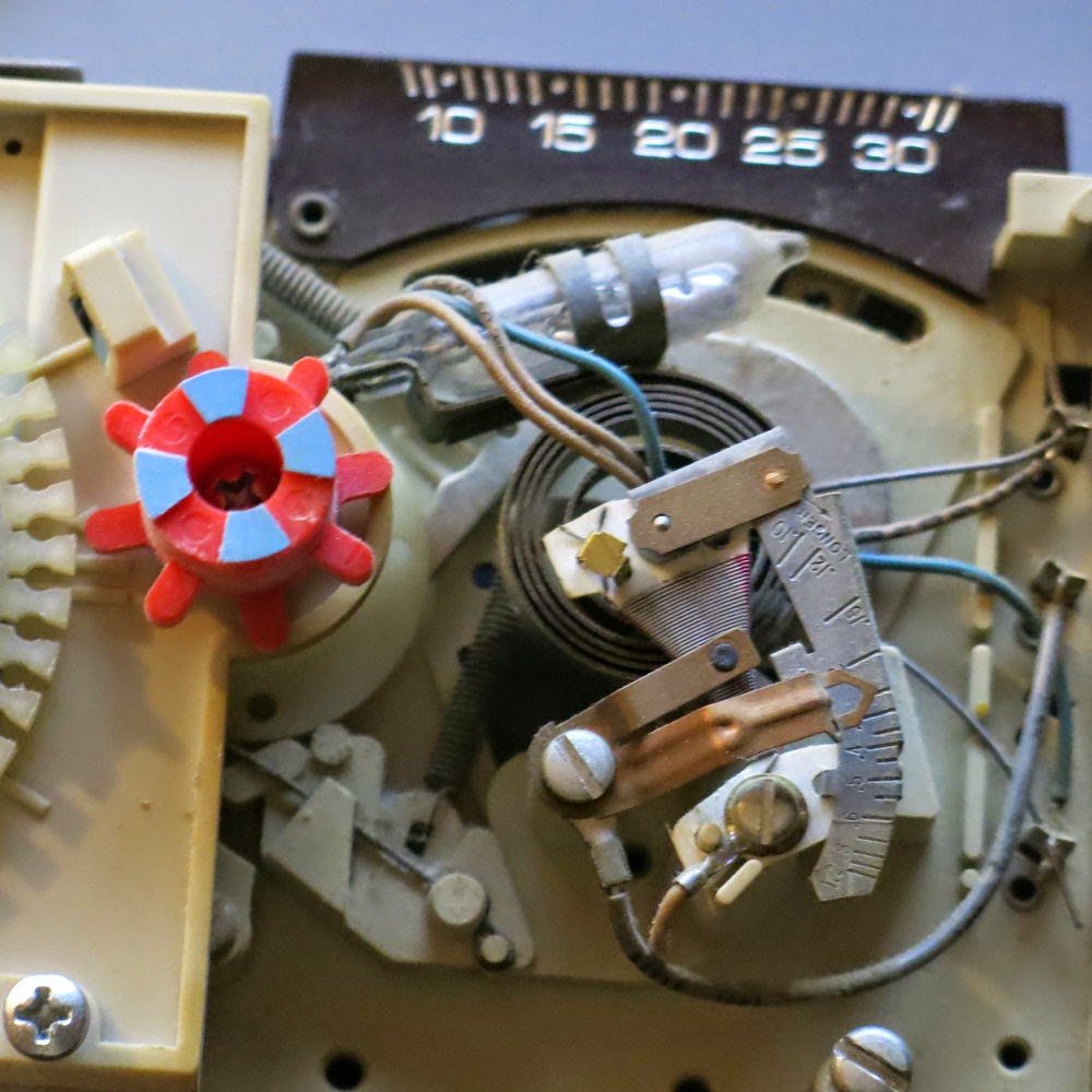
In this old Honeywell Chronotherm the single mercury switch is to the right on a tilt-able mount which is attached to the set temperature lever. The black thing with two wires hanging out the left side looks and feels like a battery. Is it possible that is a DC operated clock?

A closer view of the mercury switch, the small glass vial up and to the right to the right of the colored plastic post. I would like to remove the vial and it's wires without damage. I'll have to study it a bit and report back.

SAFETY REMINDER: Mercury is toxic and we must take a lot of care NOT TO BREAK THE VIAL and let the mercury escape. It is best to work over a pan so that should the vial be damaged, the mercury will escape into the pan. Keep a pill bottle handy for any escaped mercury metal.

In North America, you are more likely to see round Honeywell thermostats, like the T87 (complete data sheet here). It comes apart easily by undoing the single long screw that holds the adjustment post in place.

Recently, I rescued three T87 from a lighthouse that had new heating installed. Thank you Cabot Head. Three is ideal since if I have trouble with any one I will still have the two I need.

When I removed these from the wall, I did not know that there were three screws to remove the dome from its base so some damage resulted, mostly to a metal wiring terminal post but that won't matter for removal of the mercury switch.

Here is the T87 dis-assembled with the mercury switch on its thermal spring. The wire terminals are clean and undamaged. The drop of mercury is in the glass vial which is not chipped or cracked. With this one, the glass vial can be separated from the mounting clip, it just slides out the fingers, they haven't used any glue. But I think that we can make use of the clip assembly to mount our mercury switch.

Could we use the whole tilt-able mount assembly to have a fine adjustment built in to our own mount? For what I have in mind I don't want temperature to be a factor so I would like to replace all or most of the bi-metal spring which is the sensing element for temperature in this thermostat. Newer ones use a thermistor or a semiconductor sensing element and they don't contain a mercury switch.

One possible use of these type of switches is for limit switches in a solar tracking array or for a float switch.

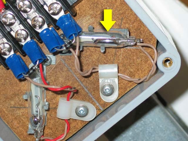
Mercury switches (in the box at the red arrow) are used to limit the rotation of the array in the pic of a parabolic solar collector.

Two mercury switches cut off motor current when the array tilts over as far as it should go. To go further will cause metal parts to jam together. Stalling the motor uses a lot of power uselessly so it is best to avoid hitting the mechanical limit. The mercury switches help prevent that.

It is not possible to easily buy mercury switches since they have all but been banned for new construction. However by gathering these as they are being removed from service saves them from the landfill and keeps them available for a future use.

Link here goes to the motor drive of the project. The main index is diy solar parabolic trough gen2 intro

George Plhak
Lion's Head, Ontario